PCBA testing is a critical quality control practice in Electronic Manufacturing(EMS), ensuring that PCB Assembly(PCBA) meets design specifications and perform reliably in real-world use. Uncontrollable factors during production—such as solder defects, component misalignment, or firmware errors—make rigorous testing essential to avoid field failures. This guide breaks down the core PCBA tests, step-by-step testing process, and best practices for maintaining quality.
1. Core PCBA Tests Explained
PCBA testing requirements vary by product complexity and customer specifications, but three foundational tests are universally critical for validating performance and reliability:
1.1 ICT (In-Circuit Test)
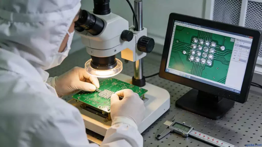
ICT (In-Circuit Test) uses precision probes to contact test points on the PCBA, detecting open circuits, short circuits, and faulty component soldering. It delivers high accuracy, clear failure diagnostics, and broad applicability across consumer, industrial, and automotive electronics.
- Key Benefit: Identifies manufacturing defects early, reducing rework costs and ensuring electrical connectivity.
1.2 FCT (Functional Circuit Test)
FCT (Functional Circuit Test) simulates real-world operating conditions to validate PCBA performance, including testing environmental tolerance, current/voltage stability, pressure responsiveness, and functional logic. This comprehensive test ensures all parameters align with the designer’s intended specifications.
- Key Benefit: Confirms the PCBA functions as intended in end-use scenarios, catching performance issues that ICT may miss.
1.3 Aging Test
Aging testing involves continuous power cycling of the PCBA to simulate long-term user scenarios, exposing latent defects (e.g., component degradation, thermal fatigue) that may not appear in initial tests. It verifies product lifespan and stability under prolonged operation.
- Key Benefit: Reduces post-shipment failures by validating reliability over time, critical for high-reliability applications like medical devices or aerospace systems.
2. Standard PCBA Testing Process
A structured testing workflow ensures consistency and thoroughness. The typical PCBA testing process aligns with customer quality plans and includes four core steps:
- Program Burning: Engineers flash firmware to the PCBA’s microcontroller, enabling it to execute specific functions before hardware validation.
- ICT Test: Probe-based electrical testing to identify soldering defects and connectivity issues.
- FCT Test: Functional validation under simulated operating conditions to confirm performance.
- Aging Test: Long-term stress testing to ensure stability and lifespan.
After passing all tests, qualified PCBA boards are labeled, packaged, and shipped to customers.
3. PCBA Manufacturing & Assembly Flows
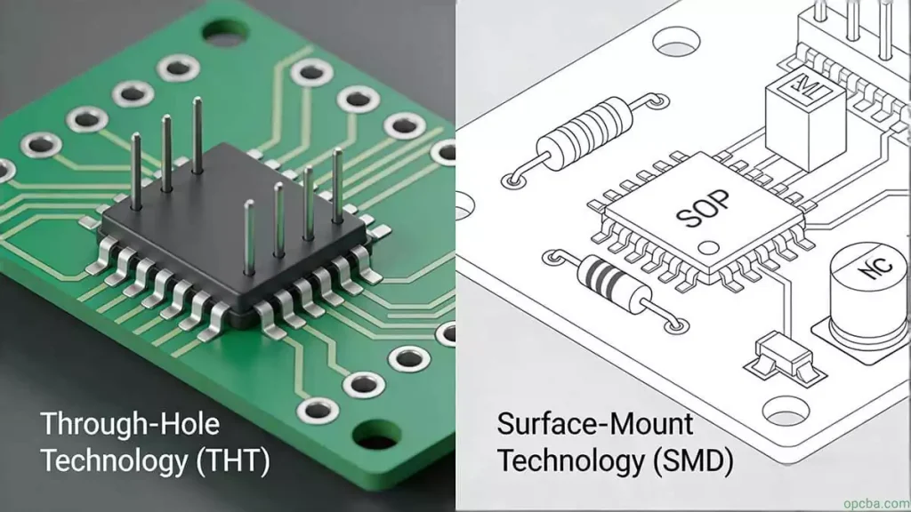
Understanding the full PCBA production context helps optimize testing efficiency. Key assembly processes include:
- Single-Sided Surface Mount: Solder paste printing → component placement → reflow soldering
- Double-Sided Surface Mount: A-side printing → placement → reflow → flip → B-side printing → placement → reflow
- Single-Sided Mixed Packaging (SMD + THC on one side): Solder paste printing → placement → reflow → manual THC insertion → wave soldering
- Double-Sided Mixed Packaging (SMD + THC on both sides): B-side red glue printing on the Printed Circuit Board(PCB) → placement → curing → flip → A-side insertion → B-side wave soldering
Critical Quality Checks During Production
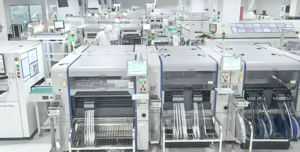
Machinery and equipment are the most consistent variables in soldering processes, so prioritize their calibration:
- Use independent electronic instruments (e.g., thermometers, multimeters) to verify temperature profiles and machine parameters
- Regularly inspect solder paste printers and pick-and-place machines to prevent alignment errors
4. FAQ About PCBA Testing
- What is the difference between ICT and FCT testing? ICT focuses on electrical connectivity and soldering defects, while FCT validates functional performance under real-world conditions.
- Why is aging testing important? It exposes latent defects that initial tests miss, ensuring long-term reliability in high-demand applications.
- How do I choose the right PCBA tests for my product? Align tests with your product’s use case—e.g., aerospace systems require rigorous aging testing, while consumer electronics may prioritize speed and cost efficiency.