Description
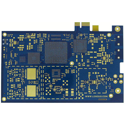
High speed PCB is a special kind of printed circuit board, mainly used in high-speed digital circuits, which is needed to ensure the integrity of signal transmission. Digital circuit rate of 45MHZ ~ 50MHZ, and this part of the rate of the signal accounted for more than one-third of the entire system, known as high speed PCB. High speed PCB in the design of signal integrity specifications is more stringent than the other design, in addition to the design to meet the requirements of the material selected to meet and ensure the stability of the signal.
Because the board itself is an important part of the signal integrity, the board material used for high-speed design needs to have properties such as dielectric constant with tight tolerances to help control impedance. If the impedance is allowed to vary throughout the design, then high-speed signals will begin to reflect energy as they travel through the line, and the signal will be distorted. Again, a low dissipation factor is expected to help maintain signal integrity. Finally, thermal stability is another important characteristic to ensure that dielectric properties are not destroyed.
High-speed PCBs are characterized by high signal transmission rates, low signal attenuation, low crosstalk, and low noise to meet the signal integrity and EMC requirements of high-speed digital circuits.
1. Advantages of high speed PCB
(1) Reduce signal loss. As the frequency of the transmission line increases, signal loss becomes a bigger problem. High-speed design plate materials have much lower dissipation factors than FR-4, with some materials (such as nearly pure PTFE laminates) being an order of magnitude better. These lower dissipation factors are an important factor in reducing signal loss.
(2) Tighter impedance control. Conventional PCB materials (such as FR-4) do not provide the same precise control over dielectric constant (Dk) as high-speed board materials. FR-4 Dk varies by +/- 10% or more, while materials such as PTFE keep their Dk tolerances at +/- 2% or more.
(3) Better Thermal Management. Some high-speed design board materials (e.g., thermoset hydrocarbon laminates) have much better thermal conductivity than FR-4. If your design is going to deal with thermal management issues, then these board materials are the ones to look into.
(4) Increased water absorption. Water has dielectric properties, and even a small amount of moisture absorbed into a PCB with high-frequency circuits can change the electrical properties of those circuits. Although the moisture absorption rate of FR-4 is close to 50%, some PTFE materials have moisture absorption rates as low as 2%, and consideration should be given to solving this problem.
(5) Robust dimensional stability. For dense, high-speed designs with tight tolerances, the need for dimensional stability increases. Although FR-4 is known for its dimensional stability, it lacks the other advantages offered by high-speed materials. In this case, thermoset hydrocarbon laminates may be a better choice.
2. Designing high speed PCBs requires attention
(1) Signal integrity, SI.
Signal integrity refers to the quality of the signal in the transmission path, which can be a normal metal wire, an optical device, or another medium. In the case of short distances and low bit rates, a simple conductor can transmit the signal realistically. In contrast, if a long-distance, high-bit-rate signal passes through several different conductors, multiple effects can reduce the credibility of the signal so that the system or device does not work properly.
As the output switching speed of integrated circuits increases and the density of PCB boards increases, signal integrity has become one of the issues that must be considered with high-speed digital PCB design. Factors such as the parameters of components and PCB boards, the layout of components on PCB boards, and the wiring of high-speed signals can cause signal integrity problems, resulting in unstable system operation or even complete non-operation.
The main issues to be considered for signal integrity are ringing, crosstalk, ground bounce, skew, signal loss, and noise in the power supply.
(2) Reflection
A reflection is an echo on a transmission line. A portion of the signal power (voltage and current) is transmitted over the line and reaches the load, but a portion is reflected. If the source and the load have the same impedance, reflections do not occur. An impedance mismatch between the source and the load causes reflections on the line, and the load reflects some of the voltage to the source.
If the load impedance is less than the source impedance, the reflected voltage is negative, and conversely, if the load impedance is greater than the source impedance, the reflected voltage is positive.
Variations in wiring geometry, incorrect line termination, transmission through connectors, and discontinuities in the power plane can cause such reflections.
(3) Crosstalk
Crosstalk is the coupling between two signal lines, the mutual inductance and mutual capacitance between the signal lines cause noise on the line. Capacitive coupling is triggered by the coupling current, while inductive coupling is triggered by the coupling voltage. PCB board parameters, signal line spacing, the driving end and the receiving end of the electrical characteristics, and line termination have a certain impact on the crosstalk.
(4) Characteristic impedance
The input impedance at the beginning of the transmission line is referred to as impedance;
The timely impedance encountered by the signal at any time is called the instantaneous impedance;
If the transmission line has a constant instantaneous impedance, it is called the characteristic impedance of the transmission line.
Characteristic impedance describes the transient impedance to which a signal is subjected as it propagates along a transmission line, and it is a major factor affecting the integrity of signals in transmission line circuits.
(5) Power integrity
Power integrity, PI, is the ability to verify that the voltage and current at the source and destination of the power supply meet the requirements. Power integrity is very important in today's electronic products. There are several levels of power integrity: chip level, chip package level, board level, and system level. Power integrity at the board level has to meet the following three requirements: make the voltage ripple at the chip pins smaller than the specification (e.g., the error between voltage and 1V is less than +/-50 mV); control the ground bounce; reduce the electromagnetic interference (EMI) and maintain the electromagnetic compatibility (EMC): Power Distribution Networks (PDNs) are the largest conductors on the board, and therefore are the antennas most prone to transmitting and receiving noise. receive noise from the antenna.
(6) Power supply noise
Power supply noise is a kind of electromagnetic interference, the spectrum of its conduction noise is roughly 10kHz ~ 30MHz, up to 150MHz. power supply noise, especially transient noise interference, its fast rise, short duration, high voltage amplitude, randomness, microcomputer, and digital circuits are prone to serious interference.
In high-frequency circuits, the power supply with the noise on the high-frequency signal is particularly obvious. Therefore, the first requirement is that the power supply is low noise. Here, clean ground is as important as a clean power supply.
In addition, filtering, parallel buses, serial buses, and topologies must be taken into account in high-speed PCBs.
High speed PCBs are mainly used in high-speed digital circuits such as switches and AI servers, and the upgrade of AI server/EGS platforms is driving the demand for high-speed PCBs. At present, high-speed PCB has been widely used in data center switches, AI servers automotive intelligence, and other fields. In 2024 only AI servers in the value of the OAM board, UBB board, and CPU motherboard are expected to bring 1 billion U.S. dollars of incremental market, the EGS platform to increase the penetration rate is also expected to open up new market space.
分享到: