Description
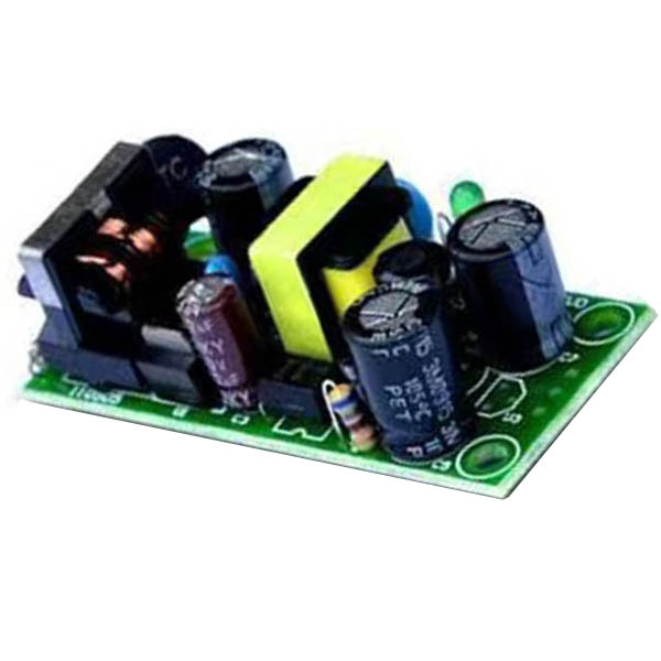
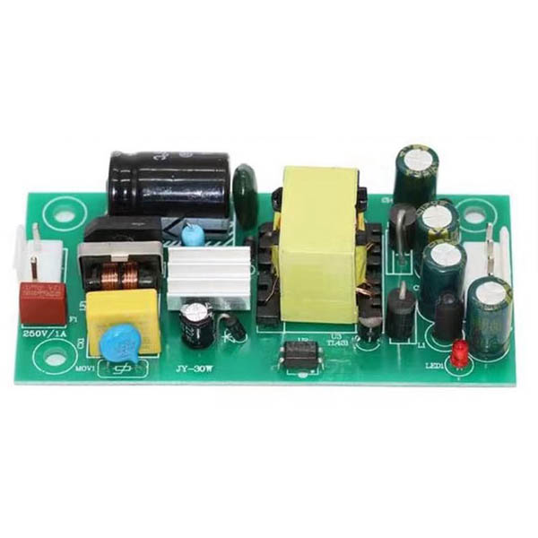
Power supply PCBA is an electronic board that mainly deals with power supply, and it is widely used in various electronic products. Power supply PCBA is an electronic device that converts direct current into alternating current and is typically embedded in other electronic devices such as computers, mobile phones, etc. In power supply PCBA, electrolytic capacitors, safety capacitors, optocouplers, common mode inductors, ordinary inductors, ceramic capacitors, rectifier bridges, and switches are generally configured. Of course, there are also basic components such as transformers, diodes, and transistors that are always equipped in common electrical appliances.
What is a power supply PCBA?
Power supply PCBA is an electronic device that provides the required energy to other electronic devices by converting electrical energy into another type of electrical energy. To achieve this function, a power supply PCBA typically includes one or more components such as transformers, capacitors, and rectifiers.
Power supply PCBA is a motherboard that processes power supplies. Power PCBA is used in many electronic products, including our computers, phones, tablets, and more. Power supply PCBA is very important for electronic products.

What is the function of power supply PCBA?
The main function of power supply PCBA is to provide the required electricity for other devices and ensure the stability and reliability of the electricity. Different types and specifications of power supply PCBAs can be customized according to needs to meet the needs of different power, voltage, and current devices.

What is the working principle of power supply PCBA?
1. After being powered on, the secondary power supply starts working first, providing a positive 5V working voltage to the main circuit board microprocessor control system.
2. After starting up, the secondary power supply provides VCC-ON power to the PFC power factor correction circuit driver control circuit and the main switch power supply driver giant circuit. The main switch power supply starts working and provides two types of voltages, positive 24V and positive 12V, to the load circuit of the main circuit board.
3. After filtering out the clutter interference in the mains power through anti-interference circuits, rectification, PFC inductance, and filtering output 300V DC voltage to the secondary power supply circuit, and the secondary power supply starts to work and output+5V voltage.
4. Connect pin 1 of the power supply PCBA output socket to the digital board CPU circuit, and the CPU circuit reads the data to output a high-level startup voltage.
5. Connect pin 2 of the power supply PCBA to the power supply PCBA voltage stabilizing power on/off control circuit. The power on/off control circuit operates, outputs voltage to the PFC oscillation circuit, and outputs high-frequency square pulse to drive the PFC switching transistor to work. Utilize the reverse pulse generated by the PFC inductor.
6. After rectification and filtering, a PFC voltage of 400V is generated. The PFC voltage is sent to the main power supply circuit and PFC voltage detection circuit. The PFC detection circuit detects that the PFC voltage reaches 400V, and the PFC detection switch circuit outputs the voltage to the main power supply oscillation circuit. The oscillation circuit outputs high-frequency square wave pulses to the main power supply power switch circuit.
7. The operation of the switch tube drives the operation of the switch transformer, which outputs two sets of voltages from the secondary induction, and after rectification and filtering, outputs+12V and+24V voltages. At this point, the entire power supply PCBA startup process is complete.
8. When the TV is in standby mode, the PFC power factor correction circuit driver control circuit and the main switch power supply driver control circuit VCC-ON power supply are cut off, and the main power supply stops working.


分享到: