First of all, the use of diodes in PCBA processing is critical for reliable circuit performance. Engineers widely use diodes as fundamental electronic components, leveraging their unidirectional conductivity and stable electrical characteristics to enable core circuit functions. This article explains the 8 most common uses of diodes in PCBA manufacturing and circuit design, which are essential for understanding the broader context of PCB Assembly(PCBA).
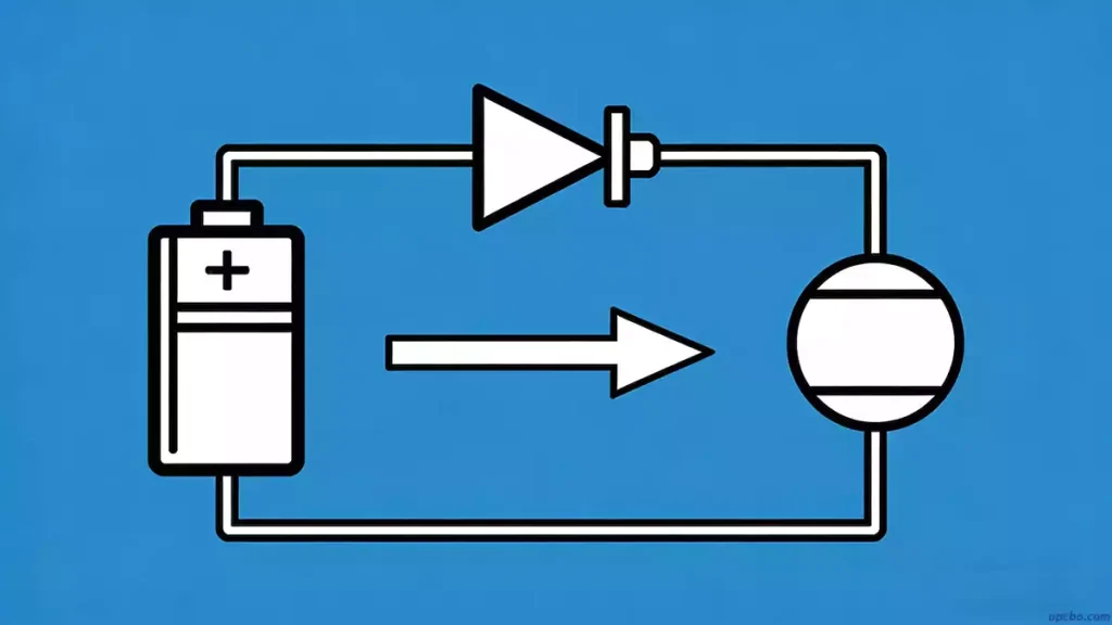
1. Anti-Reverse Connection Protection
Furthermore, anti-reverse connection protection stands as one of the most basic applications of diodes in PCBA processing. By connecting a diode in series in the main circuit, designers use its unidirectional conductivity to build a simple, low-cost anti-reverse circuit. This method is widely used in low-current devices such as small electronic toys. Silicon diodes have a forward voltage drop of about 0.7V. High current will cause power loss and heat. If the reverse voltage exceeds the diode’s reverse breakdown voltage, the diode will fail and lose its protective function.
2. Rectification
In addition, rectification is another key use of diodes in PCBA processing. Rectifier circuits convert low-voltage alternating current (AC) into unidirectional pulsating direct current (DC). Engineers use rectifier diodes as the core components of this process. The output after rectification is not pure DC, but a one-way pulsating DC voltage mixed with AC components. This function is essential in power supply circuits for almost all electronic products.

3. Voltage Stabilization
Specifically, voltage stabilization relies on specialized diodes called Zener diodes, a common use of diodes in PCBA processing. These diodes work in the reverse breakdown region of the PN junction. In this state, the voltage across the Zener diode stays almost constant even when the current changes over a wide range. This makes them ideal for stable reference voltage circuits in PCBA.
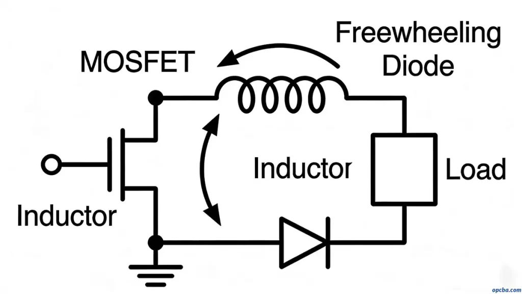
4. Freewheeling (Afterflow)
Moreover, freewheeling is a critical use of diodes in PCBA processing, especially in inductive circuits. Engineers place freewheeling diodes in parallel across inductive components such as coils and inductors. When the current through an inductor is cut off, it generates a high induced electromotive force. This high reverse voltage can damage transistors and other parts. The freewheeling diode provides a discharge loop for the inductor. It consumes the induced electromotive force and protects other components in the circuit. This function is very common in BUCK converter circuits and switching power supplies.
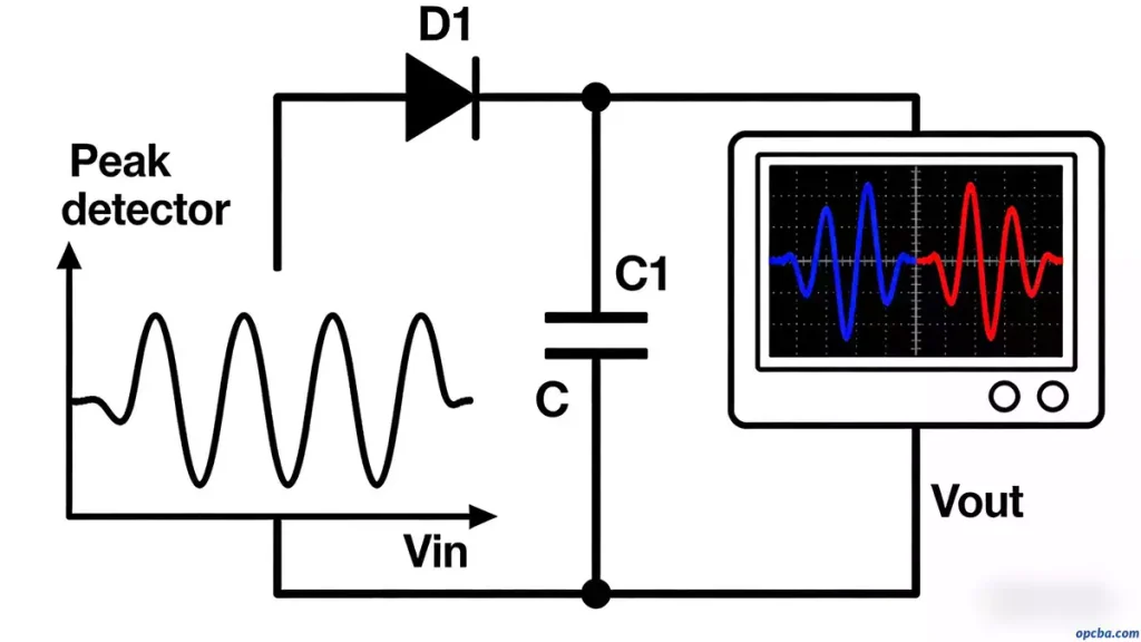
5. Peak Detection
Additionally, peak detection is another important use of diodes in PCBA processing. Peak detection circuits capture and maintain the maximum amplitude of an input signal. When the input voltage exceeds the diode’s forward voltage, the diode turns on and charges the capacitor. When the input voltage drops, the diode turns off. The capacitor holds the peak voltage until a higher input signal arrives. This structure is often used in signal sampling and measurement circuits.
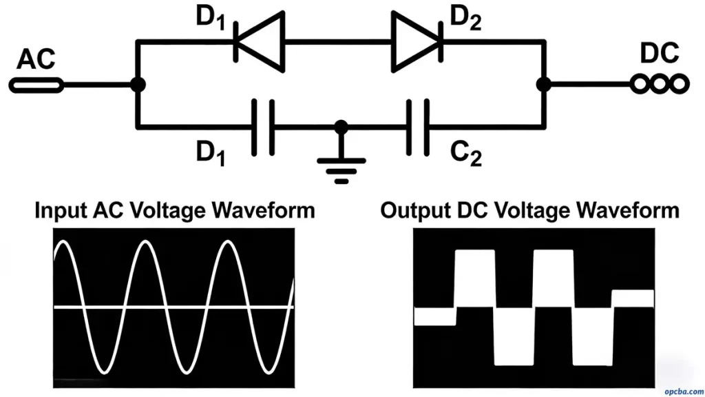
6. Voltage Doubling
For example, voltage doubling circuits use diodes and capacitors to increase the output voltage, a specialized use of diodes in PCBA processing. In the negative half-cycle of the AC power supply, diode D1 conducts and charges capacitor C1. In the positive half-cycle, the voltage of C1 superimposes with the input voltage. This turns on D2 and charges C2 to nearly double the input peak voltage. Multi-stage voltage doubling circuits can achieve even higher output voltages.
7. Voltage Clamping
Furthermore, voltage clamping is a protective use of diodes in PCBA processing, especially in ADC detection circuits. Engineers use two diodes to limit the input voltage within a safe range. With a 0.7V forward voltage drop, one diode clamps the upper limit and the other clamps the lower limit. This prevents overvoltage from damaging rear-end chips and components.
8. Envelope Detection
Finally, envelope detection is a specialized use of diodes in PCBA processing for signal demodulation. This circuit extracts the low-frequency modulation signal from a high-frequency carrier. The RC time constant is the key design parameter. It must be much longer than the carrier period and much shorter than the modulation signal period. This diode-based circuit is widely used in wireless communication and signal demodulation modules in PCBA. For more detailed insights into designing robust PCBA systems, especially for robotic applications, refer to our guide on Robot PCBA: Design Precautions & Manufacturing Guidelines.