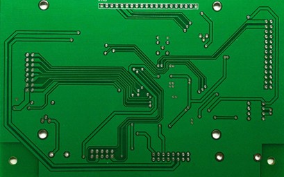
Via is one of the most important parts of a multilayer PCB, and the cost of drilling usually accounts for 30% to 40% of the cost of PCB fabrication. From the design point of view, a via is mainly composed of two parts, one is the middle of the drill hole (drill hole), and the second is the drill hole around the pad area, the size of these two parts of the size of the decision of the size of the via.

Obviously, in the high-speed, high-density PCB design, designers always hope that the smaller the better the hole, so that the board can leave more wiring space, in addition, the smaller the hole, the smaller its parasitic capacitance is also more suitable for high-speed circuits. However, the reduction of the hole size at the same time brings an increase in cost, and the size of the hole can not be an unlimited reduction, it is subject to drilling (drill) plating (plating), and other processes.
It is subject to drilling (drill) and plating (plating) and other process technology limitations: the smaller the hole, the longer it takes to drill, but also more likely to deviate from the center; and when the depth of the hole is more than 6 times the diameter of the hole, it is impossible to ensure that the walls of the hole can be uniformly plated with copper.
Comprehensive design and production, need to consider the following issues. ultra-thin pcb all-pcbs.com
1. All through the hole inner diameter in principle requires 0.2mm (8mil) and above, and the outer diameter of 0.4mm (16mil) or more, there are difficult places that must be controlled in the outer diameter of 0.35mm (14mil); according to the experience of the PCB commonly used through the hole size of the inner diameter and the size of the outer diameter of the general follow the X * 2 ± 2mil (X indicates the size of the inner diameter). For example, 8mil inner diameter size of the aperture can be designed as 8/14mil, 8/16mil or 8/18mil; for example, 12mil aperture can be designed as 12/22mil, 12/24mil, 12/26mil;
2. BGA in 0.65mm and above is recommended not to use the design of buried blind holes, the cost will increase significantly. Used to bury blind holes when the general use of first-order blind holes can be (TOP layer - L2 layer or BOTTOM-negative L2), over the hole ID is generally 0.1mm (4mil), the outer diameter of 0.25mm (10mil).
3. Through-hole can not be placed in less than 0402 resistance tolerance pad size on the pad; theoretically placed in the pad on the lead inductance is small, but the production of the candidate, the paste is easy to go into the hole, resulting in uneven paste caused by the phenomenon of the device stand up ('monument' phenomenon). Generally recommended spacing of 4-8mil.
4. The distance between the hole and the hole should not be too close, drilling is easily caused by broken holes. General requirements for hole spacing 0.5mm and above, 0.35mm-0.4mm to avoid, 0.3mm and below is prohibited. 5;
5. In addition to heat dissipation over the hole, ≤ 0.5mm over the hole, need to plug the hole cover oil (inner diameter is 0.4mm within the need to plug the hole).
(1) In particular, the device has a metal shell, the principle of the body does not play under the hole, played the hole must be plugged hole cover oil, so as not to cause the shell and the hole to short circuit.
(2) According to the board factory production feedback, it will often be mentioned that the BGA hole from the pad is too close to the need to move the hole.
This situation is due to the hole not being the distance from the BGA pads caused by equidistant, due to the current BAG under the hole, test hole location is not the distance from the BGA pads is a norm, PCB designers do not pay attention to this, resulting in constant engineering problems, the quality of the weld is also a hidden danger. Therefore, it is recommended that Hole punching to the center of the two pads, especially inside the BGA due to the Pitch spacing being small, after punching also need to BGA under the hole plug hole cap Oil, so as not to easily cause the BGA ball even in short circuit.
6. headphone terminals, buttons, FPC, and other fixed pads to prevent the pad's copper skin off, under the conditions that allow the pads to play 1-2 holes (holes evenly Placement), can effectively improve the "fixity".
Contact OPCBA.COM to know the information you're interested in. ultra-thin pcb all-pcbs.com

分享到: