Isola 370HR is a high-Tg epoxy laminate and prepreg system reinforced with electrical grade E-glass. If the material is new to you, start with what Isola 370HR is and come back here for the numbers. It carries more thermal margin than standard FR-4 and expands less through the Z axis, while still running on conventional FR-4 process equipment. If you have not settled whether your board needs it yet, our guide to choosing between 370HR and standard FR-4 covers that decision first.
This page is for the step after that. It lists the published property values, explains what those numbers do and do not tell you, and shows how to write the material on a fabrication drawing so the board that comes back matches the one you designed.
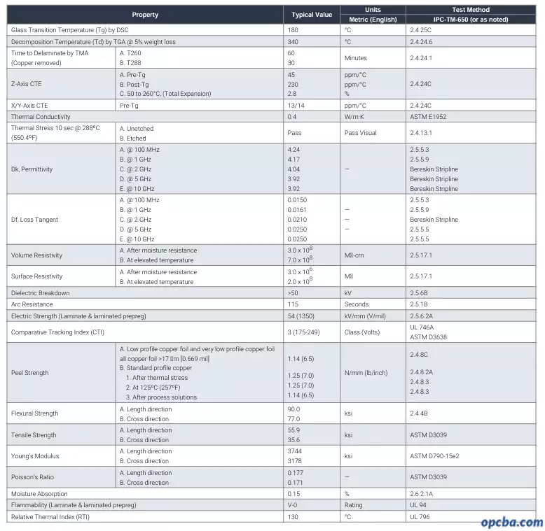
Typical property values
The figures below are typical values from Isola’s published 370HR datasheet. Confirm them against the current revision and against your supplier’s certificate of conformance before you commit a design.
| Property | Typical value | Condition or method |
|---|---|---|
| Glass transition temperature (Tg), by DSC | 180°C | IPC-TM-650 2.4.25C |
| Decomposition temperature (Td), by TGA at 5% weight loss | 340°C | IPC-TM-650 2.4.24.6 |
| Time to delaminate by TMA, T260 (copper removed) | 60 minutes | IPC-TM-650 2.4.24.1 |
| Time to delaminate by TMA, T288 (copper removed) | 30 minutes | IPC-TM-650 2.4.24.1 |
| Z-axis CTE, pre-Tg | 45 ppm/°C | IPC-TM-650 2.4.24C |
| Z-axis CTE, post-Tg | 230 ppm/°C | IPC-TM-650 2.4.24C |
| Z-axis expansion, 50 to 260°C (total) | 2.8% | IPC-TM-650 2.4.24C |
| X/Y-axis CTE, pre-Tg | 13 / 14 ppm/°C | IPC-TM-650 2.4.24C |
| Thermal conductivity | 0.4 W/m·K | ASTM E1952 |
| Thermal stress, 10 s at 288°C, unetched and etched | Pass | IPC-TM-650 2.4.13.1 |
| Relative thermal index (RTI) | 130°C | UL 796 |
| Dielectric constant (Dk) at 100 MHz | 4.24 | IPC-TM-650 2.5.5.3 |
| Dielectric constant (Dk) at 1 GHz | 4.17 | IPC-TM-650 2.5.5.9 |
| Dielectric constant (Dk) at 2 GHz | 4.04 | Bereskin stripline |
| Dielectric constant (Dk) at 5 GHz | 3.92 | Bereskin stripline |
| Dielectric constant (Dk) at 10 GHz | 3.92 | Bereskin stripline |
| Dissipation factor (Df) at 100 MHz | 0.0150 | IPC-TM-650 2.5.5.3 |
| Dissipation factor (Df) at 1 GHz | 0.0161 | IPC-TM-650 2.5.5.9 |
| Dissipation factor (Df) at 2 GHz | 0.0210 | Bereskin stripline |
| Dissipation factor (Df) at 5 GHz | 0.0250 | IPC-TM-650 2.5.5.5 |
| Dissipation factor (Df) at 10 GHz | 0.0250 | IPC-TM-650 2.5.5.5 |
| Volume resistivity | 3.0 × 10⁸ MΩ·cm after moisture resistance, 7.0 × 10⁸ MΩ·cm at elevated temperature | IPC-TM-650 2.5.17.1 |
| Surface resistivity | 3.0 × 10⁶ MΩ after moisture resistance, 2.0 × 10⁸ MΩ at elevated temperature | IPC-TM-650 2.5.17.1 |
| Dielectric breakdown | >50 kV | IPC-TM-650 2.5.6B |
| Electric strength, laminate and laminated prepreg | 54 kV/mm (1350 V/mil) | IPC-TM-650 2.5.6.2A |
| Arc resistance | 115 seconds | IPC-TM-650 2.5.1B |
| Comparative tracking index (CTI) | Class 3 (175 to 249 V) | UL 746A / ASTM D3638 |
| Peel strength, low and very low profile copper foil (>17 µm) | 1.14 N/mm (6.5 lb/in) | IPC-TM-650 2.4.8C |
| Peel strength, standard profile copper foil | 1.25 N/mm (7.0 lb/in) after thermal stress and at 125°C, 1.14 N/mm (6.5 lb/in) after process solutions | IPC-TM-650 2.4.8.2A and 2.4.8.3 |
| Flexural strength, length / cross direction | 90.0 / 77.0 ksi | IPC-TM-650 2.4.4B |
| Tensile strength, length / cross direction | 55.9 / 35.6 ksi | ASTM D3039 |
| Young’s modulus, length / cross direction | 3744 / 3178 ksi | ASTM D790-15e2 |
| Poisson’s ratio, length / cross direction | 0.177 / 0.171 | ASTM D3039 |
| Moisture absorption | 0.15% | IPC-TM-650 2.6.2.1A |
| Flammability, laminate and laminated prepreg | UL 94 V-0 | UL 94 |
| UV blocking and AOI fluorescence | Yes | Isola product attribute |
| CAF resistance | CAF resistant | Isola product attribute |
| IPC-4101 slash sheets | /98, /99, /101, /126 | IPC-4101 |
| UL recognition | File E41625, grade PCL-FR-370HR | UL |
| RoHS compliance | Compliant | EU RoHS directive |
| Copper foil types | HTE Grade 3, RTF (reverse treat foil) | Product availability |
| Copper weights | ½ to 2 oz (18 to 70 µm). Heavier and thinner on request | Product availability |
| Core thickness range | 0.05 to 3.2 mm (2 to 125 mil) | Product availability |
| Prepreg form | Roll or panel. Tooling of prepreg panels available | Product availability |
| Glass fabric options | E-glass, square weave, mechanically spread glass | Product availability |
Reading the numbers
Tg depends on how it was measured
The 180°C figure is a DSC value, measured to IPC-TM-650 method 2.4.25C. Thermomechanical analysis (2.4.24C) and dynamic mechanical analysis read the same laminate differently, and DMA reports the highest of the three, sometimes 20 to 30°C above DSC on identical material. Published comparisons of the three methods do not fully agree on where TMA sits relative to DSC, so treat any Tg number that arrives without a method attached to it as incomplete.
Comparing the Tg on one datasheet against the Tg on another only means something when both were measured the same way. A supplier quoting 180°C without stating the method has not given you a complete answer.
Dk and Df are not design numbers
Isola’s own application note on laminate dielectric properties states plainly that data sheets do not provide adequate information for design purposes. The note puts the gap between two common Dk test methods at 2.54 dB at 10 GHz, which is most of a typical 3 dB loss budget for a transmission line.
The 370HR datasheet shows the same caution in its own layout. It does not report Dk and Df across all five frequency bands by a single method: 100 MHz and 1 GHz each use a different IPC method, 2 GHz and above move to a stripline method, and the Df figures at 5 and 10 GHz come from yet another. The published values are not one sweep measured one way, so treating them as a smooth curve across frequency reads more into them than the data supports.
Every laminate datasheet carries the same limitation, because the electrical numbers move with resin content, glass style and the method used to extract them. This is not specific to 370HR. It does mean that for controlled impedance work above a few GHz, the published value is a starting point for a conversation with your supplier rather than the input you run through a field solver. Ask which method produced the number and whether data exists at your target frequency.
Typical values versus your batch
Datasheet figures are typical, not guaranteed minimums, and they shift with resin content and copper cladding. A core built with a different glass style or resin content will not land on the same Dk, even under the same trade name, so the published value describes the construction that was tested rather than every construction you can order. The certificate of conformance that ships with your material describes what you actually received. Keep it, and check it against the values you designed around.
Specifying 370HR on a drawing
Name the slash sheet, not just the brand
Writing “FR-4” on a fabrication note leaves the material choice almost entirely open, and writing only a trade name is not much better. The IPC-4101 slash sheet is what your fabricator sources against. 370HR is covered by IPC-4101 /98, /99, /101 and /126, and the right one depends on the resin content and reinforcement style your stack-up needs.
Published summaries of IPC-4101 slash sheets do not always agree with each other on the exact thresholds for /98, /99 and /101. We checked four sources and found three different Tg minimums quoted for /99 alone. Confirm the requirements against the current IPC-4101 revision and the certificate of conformance for the material you are buying, rather than against a table you found online.
Specify the copper foil type at the same time. Peel strength differs between standard and low-profile foil, which changes both impedance control and long-term adhesion.
What to check on arrival
- Tg value and the test method that produced it
- Slash sheet number and UL file number
- Copper foil type and weight
- Core and prepreg thickness against your stack-up
- Lot number, for traceability if a field issue comes up later
Where it gets used
370HR turns up in equipment that runs hot or cannot fail: telecom and networking hardware, automotive electronics including ADAS and power management, aerospace and defense avionics, industrial power conversion, and medical imaging. For background on how laminate systems are classified, our overview of copper clad laminate covers the wider picture.
FAQ
Is 370HR the same as IPC-4101 /126?
Not exactly. 370HR is qualified to several slash sheets, including /126, /98, /99 and /101. A slash sheet describes a specification with minimum requirements, not a single product, so one material can satisfy several of them.
Why do suppliers quote different Tg for similar materials?
Usually because they measured it differently. DSC, TMA and DMA give different readings on identical laminate. Ask which method produced the number before you compare.
Can I use the datasheet Dk for impedance calculations?
Use it for a first pass, then confirm with your supplier. The published value depends on resin content, glass style and test method, and at multi-gigahertz rates those variables move the result enough to matter.
Does 370HR need special processing?
No. It runs close enough to standard FR-4 that most fabricators use existing equipment. Confirm drill and lamination parameters with your fab, since they will have their own qualified recipe.
Getting a quote for a 370HR build
Send the layer count, board thickness, copper weights and reflow profile, and name the slash sheet if you have settled on one. Quoting against a specific slash sheet rather than a generic FR-4 callout is what keeps the material that arrives the same as the one you designed around. Our multilayer PCB fabrication team runs 370HR and standard FR-4 on the same lines.