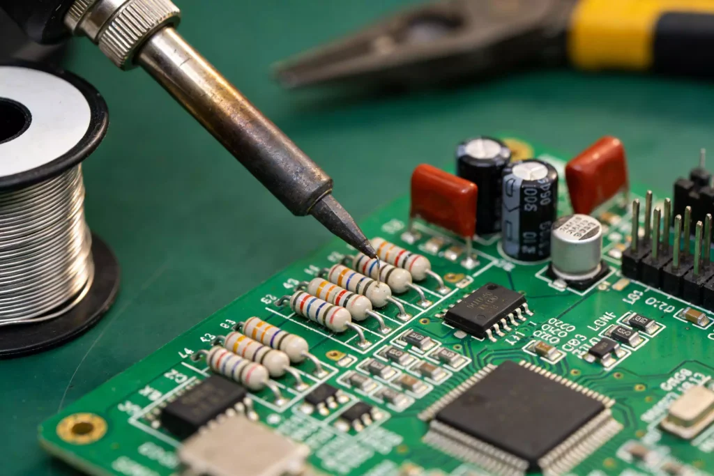
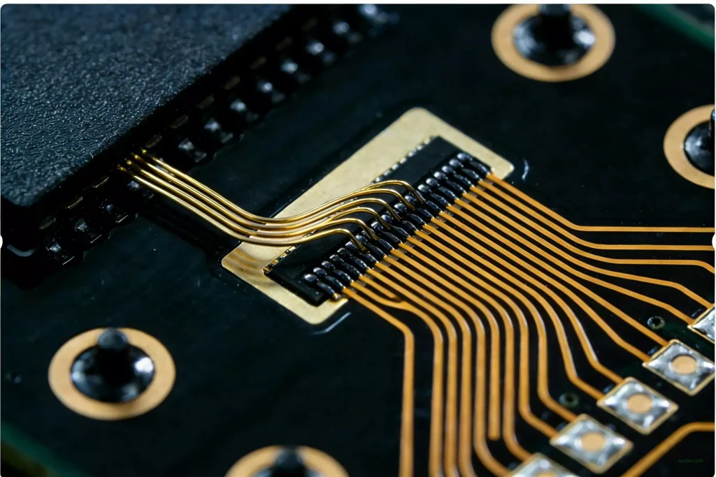
The green protective layer on finished PCBs is known as the PCB solder mask, a thin ink coating applied across most of the board surface.
Only targeted areas remain uncovered, known as solder mask windows, where copper is exposed for soldering components and surface finishing.
The rest of the board stays coated to prevent trace oxidation and electrical leakage. For a deeper dive into the basics of these core circuit boards, see our cornerstone guide: Printed Circuit Board (PCB).
Three Key Reasons for Solder Mask Windowing
Through-hole pad windowing is mandatory for assembly.
These openings let component pins attach to exposed copper during soldering; without them, ink would block the pad and make soldering impossible.
Surface-mount pad windowing serves the same purpose for SMD components.
Any ink covering these pads would render them non-functional, disrupting the entire assembly process.
Large copper surfaces also require windowing in some designs.
When a board needs higher current-carrying capacity without wider traces, direct tinning is used, and the mask must be removed in these sections.
Why Solder Mask Windows Are Larger Than Pads
Solder mask openings are always slightly bigger than the underlying copper pads for a practical production reason.
Minor alignment shifts happen routinely during PCB manufacturing, and a perfectly sized window would risk partial ink coverage on the pad.
To account for standard factory tolerances, the window is typically expanded by 4 to 6 mil around the entire pad.
This small adjustment eliminates issues caused by process deviation in actual fabrication.
SMD and NSMD: How the Window Defines the Pad
When the window is larger than the copper underneath, the pad is non-solder-mask defined, or NSMD. When the mask overlaps the pad edge and the opening is smaller than the copper, the pad is solder-mask defined, or SMD. The two behave differently under thermal cycling and mechanical load, so this is a design decision rather than a house style.
NSMD is the usual choice for fine-pitch and BGA work. The full copper area is available for the joint, and solder can wet the pad edge to form a slightly larger fillet. The trade-off is that the pad edge is left unprotected, so the copper-to-laminate bond carries more of the mechanical load.
SMD goes the other way and lets the mask anchor the pad edge, which raises peel strength and shrinks the exposed copper area. On tight pitches that smaller opening helps keep solder from reaching the neighbouring pad. The cost is a smaller wettable area, and registration error eats into it faster, because a shifted window reduces the joint area instead of merely changing the fillet shape.
BGA and fine-pitch QFN parts are usually laid out NSMD. SMD shows up where peel strength matters more than joint area, such as connectors that take insertion force, or where a narrower opening helps hold a solder mask bridge between close pads. The choice matters less than consistency: mixing the two styles on one component changes how much solder each joint takes, and that surfaces as uneven fillets during inspection.
Main Functions of the Solder Mask
The PCB solder mask prevents solder bridging during assembly, one of the most frequent causes of short circuits.
This protection becomes even more important during wave soldering, as it stops excess solder from sticking to non-soldering points.
It also creates a reliable moisture barrier, shielding circuits from humidity and slowing down oxidation over time.
Beyond this, it keeps flux residue and airborne contaminants away from the copper underneath, which matters most on boards that face long service life or humid operating conditions.
Frequently asked questions
How much larger should a solder mask window be than the pad?
The usual figure is 4 to 6 mil of expansion around the pad, which absorbs normal registration drift in fabrication. How much you actually need depends on copper weight, the imaging method used for the mask, and the surface finish being applied. When a design uses tight windows, confirm the value with the fab before the artwork is released, not after the first batch.
What is the minimum width for a solder mask bridge?
Plan for at least 0.10 mm (4 mil). If the board carries immersion tin, the tin bath attacks the ink and thins the bridge, so allow 0.125 mm (5 mil) instead. Anything narrower tends to break during development, and a broken bridge no longer separates the pads it was meant to separate.
Does solder mask color affect windowing?
Not the geometry. Window size comes from the artwork, not the pigment. But the solder mask color changes how easily a bad window shows up during inspection. White surfaces make residue and contamination obvious. Dark surfaces cut contrast, which lets a partially covered pad pass a quick visual check and still fail at AOI.