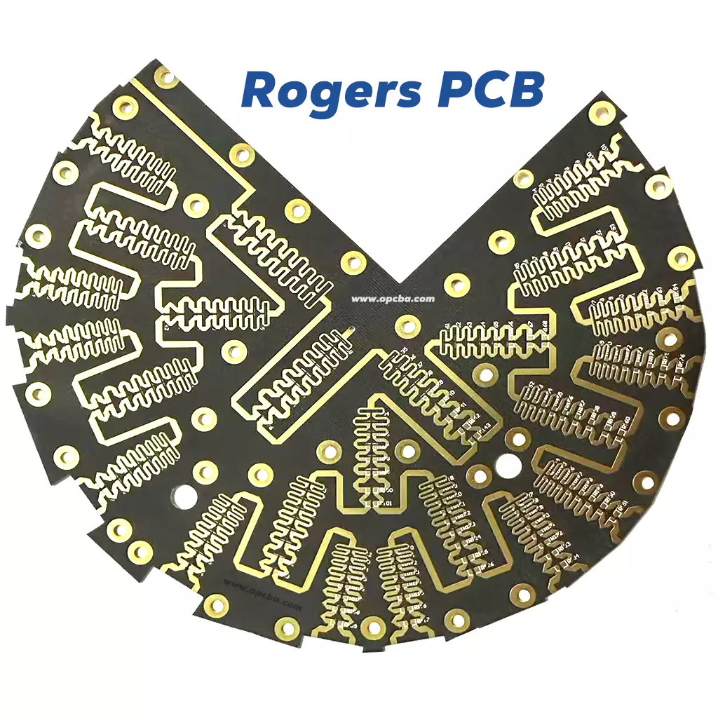
Rogers High-Frequency PCB: When Signal Integrity Is Non-Negotiable
At frequencies where FR-4 stops behaving like a dielectric and starts behaving like a heater, the substrate material becomes the single largest variable in your design. A Rogers high-frequency PCB addresses that variable at the source.
Standard FR-4 has a dissipation factor around 0.02 at 10 GHz. The Rogers materials we stock start at 0.0009—still orders of magnitude lower. That difference translates directly into lower insertion loss, less signal distortion, and tighter impedance control across temperature. For 5G base stations, satellite transceivers, automotive radar, and millimeter-wave test equipment, the substrate isn’t just a carrier. It’s a performance component.
We fabricate RF microwave PCB products across six Rogers laminates and one dedicated bonding material, from 2-layer designs to 34-layer mixed-stackup assemblies. Each material fills a specific slot in the frequency-versus-cost spectrum. Picking the right one isn’t about choosing the most expensive option. It’s about matching the dielectric constant, loss tangent, and thermal stability to what your signal actually needs.
The Rogers Materials We Work With Daily
Different applications pull different levers. Here’s how the materials in our inventory map to real design requirements.
RT5880 (Dk 2.20, Df 0.0009 at 10 GHz). A PTFE-glass laminate with one of the lowest dielectric constants available. The low Dk means wider traces for a given impedance, which reduces conductor loss. The low Df means less dielectric heating at high frequencies. This material is the standard choice for millimeter-wave modules, satellite transceivers, and airborne antenna arrays where every tenth of a decibel matters. The trade-off is cost and processing complexity—PTFE requires specialized handling during fabrication. For full deep-dive details on this ultra-low-loss substrate, check our dedicated guide: Rogers 5880 PCB: Low-Loss PTFE Composite for High-Frequency RF
RO3003 (Dk 3.00, Df 0.0010 at 10 GHz). A PTFE-ceramic composite that sits between RT5880 and the RO4000 series in both cost and performance. Dk is stable across a wide temperature range, which makes it popular for automotive radar and outdoor base station antennas where the board sees significant thermal cycling. It processes more predictably than pure PTFE laminates.
RO3010 (Dk 10.2, Df 0.0022 at 10 GHz). A high-dielectric-constant PTFE-ceramic material. The high Dk allows for significantly smaller circuit footprints at lower frequencies—useful for compact couplers, filters, and phased-array feed networks where board real estate is tight. Not a general-purpose material, but the right tool for miniaturization-driven designs. Note that this material extends our overall Dk range to 10.2, well beyond typical RF laminates.
RO4003C (Dk 3.38, Df 0.0027 at 10 GHz). A hydrocarbon-ceramic laminate that processes similarly to FR-4—no special PTFE handling required. This material hits a sweet spot for cost-sensitive RF designs that still need controlled impedance and low insertion loss. Common in power amplifiers, couplers, and phased-array feed networks in telecom equipment. Note: RO4003C is not UL 94 V-0 rated; for applications requiring a V-0 flame rating, consider RO4350B or RO4233.
RO4350B (Dk 3.48, Df 0.0037 at 10 GHz). The workhorse of the RO4000 series. Slightly higher Dk and Df than RO4003C, but fully compatible with standard PCB fabrication processes and UL 94 V-0 rated. It’s the go-to for commercial RF products where performance requirements are real but budgets are finite. If a design team is moving from FR-4 to their first low loss PCB, this is often where they land.
RO4233 (Dk 3.33, Df 0.0027 at 10 GHz). A high-thermal-conductivity variant in the RO4000 family, designed for applications where both RF performance and heat dissipation matter—think high-power amplifiers and active antenna modules where the board itself must help pull heat away from the components. Also UL 94 V-0 rated.
RO4450F (Dk 3.54, Df 0.0038 at 10 GHz). Unlike the other materials listed, RO4450F is a bonding ply (prepreg), not a core laminate. It is used in multilayer constructions to bond Rogers cores together or to bond Rogers layers to FR-4 in hybrid stackups. RO4450F is halogen-free, high-Tg, and UL 94 V-0 rated. It is commonly paired with RO4350B or RO4003C cores to build multi-layer Rogers high-frequency PCB stacks without introducing thermal reliability issues.
A practical note from the fab floor: the material choice doesn’t just affect electrical performance. It changes the etching process, the lamination cycle, and the drilling parameters. PTFE-based materials like RT5880 and RO3003 require different hole-wall preparation than hydrocarbon-ceramic materials like RO4350B. A stackup that mixes both families—say, RO4350B for the digital layers and RT5880 for the RF layer—needs careful CTE matching during lamination. We do these hybrid builds routinely, but they take longer and cost more than a single-family stackup.
What You Can Specify
Our standard Rogers high-frequency PCB capability covers:
-
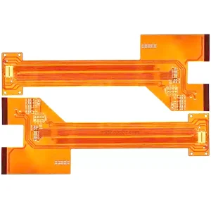
Board thickness: 0.1 mm to 12.0 mm. The thin end suits flexible or semi-flexible RF interconnects; the thick end supports large-format antenna panels and mechanically rigid assemblies.
-
Layer count: 2 to 34 layers. Double-sided RF boards are common for antennas and simple amplifier circuits. Multilayer stacks above 8 layers typically mix Rogers materials on the RF layers with FR-4 or other low-cost laminates on the digital and power layers, using RO4450F prepreg for bonding.
-
Dielectric constant: 2.2 to 10.2 across the six core materials. Low Dk widens trace widths and reduces conductor loss. Higher Dk (like RO3010 at 10.2) shrinks the footprint for compact designs. The right value depends on your frequency, your impedance targets, and your mechanical constraints.
-
Dissipation factor: 0.0009 to 0.0040 at 10 GHz. For millimeter-wave and high-power applications, stay at the low end of this range. For sub-6 GHz commercial products, the mid-range materials provide measurable performance improvement over FR-4 without the PTFE premium.
-
Flame retardant grade: V-0 for RT5880, RO3003, RO3010, RO4350B, RO4233, and RO4450F. RO4003C is not UL 94 V-0 rated; please specify if V-0 is a requirement.
-
Solder mask color: Green, black, or blue. Green is the default. Black is chosen when the board is visible. Blue is available for visual differentiation.
-
Silk screen color: White or black, selected for contrast against the solder mask.
-
Copper weight: 0.5 oz to 4 oz. Thin copper for fine-pitch RF traces; thick copper for high-current bias lines and power planes.
-
Minimum trace/space: 3 mil. At this dimension on PTFE materials, etch factor control becomes the dominant process variable. We hold tighter tolerances on RF microwave PCB orders than on standard FR-4 because the impedance sensitivity demands it.
-
Surface finish: Immersion gold (ENIG) or OSP. ENIG is the standard choice for low loss PCB applications—it provides a flat, oxidation-resistant surface for SMT assembly and consistent RF performance at the pad level. OSP is an option when cost is the primary driver.
Design Considerations for Rogers Boards
Impedance control is the starting point, not an afterthought. On a Rogers board, the dielectric constant is stable enough that impedance is primarily a function of trace geometry and dielectric thickness. We calculate trace width and spacing from your target impedance and the specific laminate’s Dk at your operating frequency. If your design calls for 50Ω single-ended or 100Ω differential, provide the stackup requirements early so we can verify the numbers before fabrication begins.
Mixed-stackup thermal management. When Rogers and FR-4 share a stackup, the two materials expand at different rates during lamination and reflow. The difference isn’t large enough to cause delamination in a properly designed stackup, but it must be accounted for in the layer ordering and the choice of prepreg (such as RO4450F). Symmetrical constructions—where Rogers layers are balanced across the centerline—reduce the risk of warpage.
PTFE handling. PTFE-based laminates (RT5880, RO3003, RO3010) require plasma treatment of drilled holes before copper plating. Without this step, the hole wall won’t wet properly and via reliability suffers. This is standard procedure in our shop, but it adds processing time compared to hydrocarbon-ceramic materials.
Copper surface preparation. Rogers materials use a proprietary treatment on the copper foil to ensure adhesion to the dielectric. Aggressive etching or rework can degrade this bond. If your design includes large copper pours or heavy ground planes, we balance the pattern with thieving to maintain etch uniformity across the panel.
Applications
Our Rogers high-frequency PCB products go into 5G communication base stations and small cells, RF microwave backhaul links, automotive and aviation radar modules, satellite communication transceivers and antennas, and general high-frequency test and measurement equipment. If your signal is above 1 GHz and your link budget is tight, the substrate conversation starts here.
Ordering
This is a custom product. Every RF microwave PCB we build is defined by your frequency plan, your impedance requirements, and your mechanical constraints—not by a stock configuration.
To get a quotation, send your Gerber file and stackup requirements to sales@opcba.com. Specify which Rogers material you need, your target impedance values, the surface finish, and your order quantity. We’ll return a formal quote with a lead time and a DFM review as soon as the engineering assessment is complete.