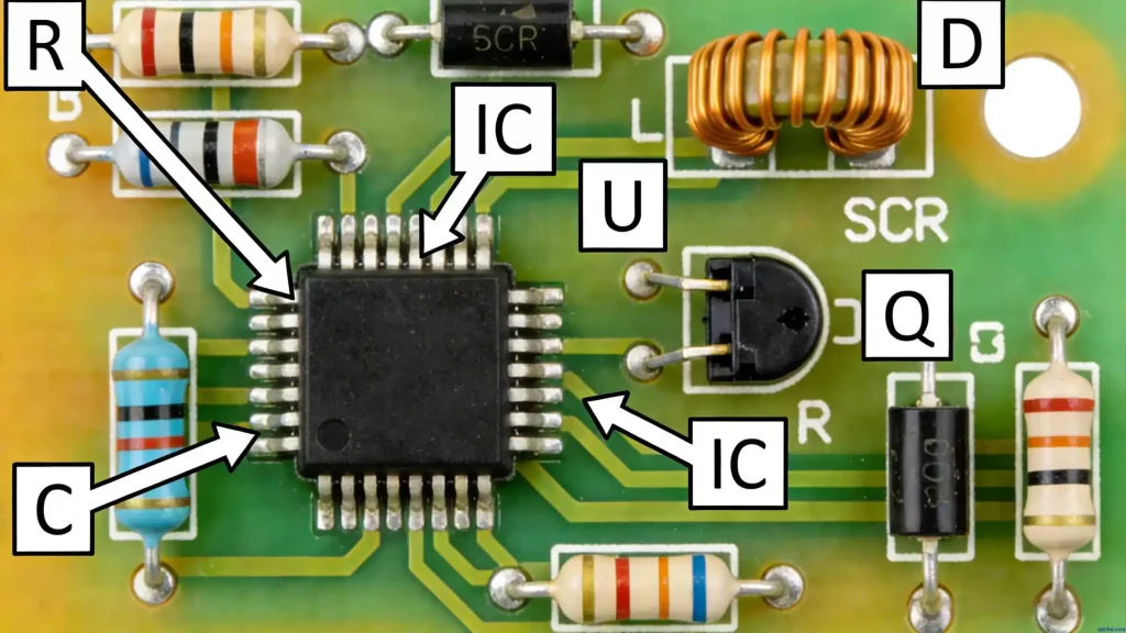
millimeter wave radar drives a growing share of modern sensing. It handles detection, ranging and speed measurement across industries that need all three at once.
It keeps working where optical sensors struggle. Low visibility, extreme temperatures and vibration leave its readings intact, which is why automotive ADAS, aerospace navigation and industrial monitoring all rely on it.
The reliability of millimeter wave radar depends on the boards inside it. High-frequency signal transmission and power management both sit on the PCB fabrication, so material choice and layout quality set the ceiling on what the system can do.
Unlike conventional microwave radar, millimeter wave radar operates in the 24 GHz to 81 GHz band. Shorter wavelengths deliver higher resolution in a smaller package, and that frequency range is what puts the pressure on board design.

Key Applications of Millimeter Wave Radar Across Industries
The same sensor works across sectors that have almost nothing else in common, and every one of them depends on how well the board is built.
Automotive ADAS
It sits behind automotive safety features such as adaptive cruise control and automatic emergency braking. Most of these systems run at 77 GHz for long and short-range detection, and the boards are built to ISO 26262 requirements so that temperature swings and vibration do not shift the readings.
Aerospace and Defense
In aerospace and defense the same sensors support helicopter fire control and satellite navigation, where radiation, vacuum and extreme temperatures are the normal operating conditions. Boards for these systems use radiation-hardened materials and are built to MIL-STD-810.
Industrial and Civil Infrastructure
Industrial deployments use them to watch debris flow, bridge deformation and traffic conditions, which calls for long-range sensing and weather resistance. High-thermal substrates and shielded enclosures are the usual answer.
Core Technical Principles of Millimeter Wave Radar
The radar transmits high-frequency waves and analyzes what comes back, building a point cloud that gives target distance, speed and direction. Transmitter, receiver and processor all sit on the board, which is where the technical requirements concentrate.
Frequency Band Matching
Common bands are 24 GHz for short range and 77 GHz to 81 GHz for long range, and each needs different board materials. 24 GHz systems can use high-frequency FR-4, while 77 GHz sensors need a low-loss laminate such as Rogers 4350B.
MIMO Technology
MIMO raises both resolution and coverage, but it needs tight trace spacing and 50Ω impedance control to keep channels from coupling. That is where layout discipline shows up in the final measurements.
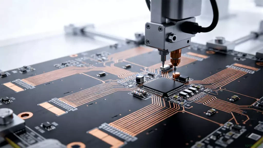
PCB/PCBA Design for Millimeter Wave Radar
Designing PCBAs for these sensors takes expertise on both the layout and the assembly side. The radar PCB design rules that govern impedance, stackup and shielding set the target, and assembly has to hold it.
1. High-Frequency PCB Design
- Impedance Control: We maintain 50Ω/75Ω impedance across RF traces to minimize signal loss.
- Trace Routing: Short, wide traces reduce resistance. Power and signal traces are separated to prevent EMI.
- Low-Loss Materials: Rogers 4350B and PTFE substrates keep signal integrity intact at these frequencies.
2. Precision PCBA Assembly
- High-Precision Soldering: Lead-free SMT reflow soldering keeps joint resistance low, which is what high-frequency signals need.
- Component Validation: All RF components undergo testing to meet performance requirements.
- EMI Shielding: Custom enclosures protect sensitive RF sections from interference.
Future Trends of Millimeter Wave Radar
These high-frequency sensors are evolving to higher frequencies (up to 140 GHz) and smaller form factors. This drives innovations like embedded antennas and flexible PCBs. HDI processing is where the next round of improvement sits.
EMS and assembly services cover the step between finished boards and a working radar module, which is where millimeter wave designs most often lose the performance the layout was built for. Whether the target is automotive ADAS or aerospace defense, that step matters as much as the design.