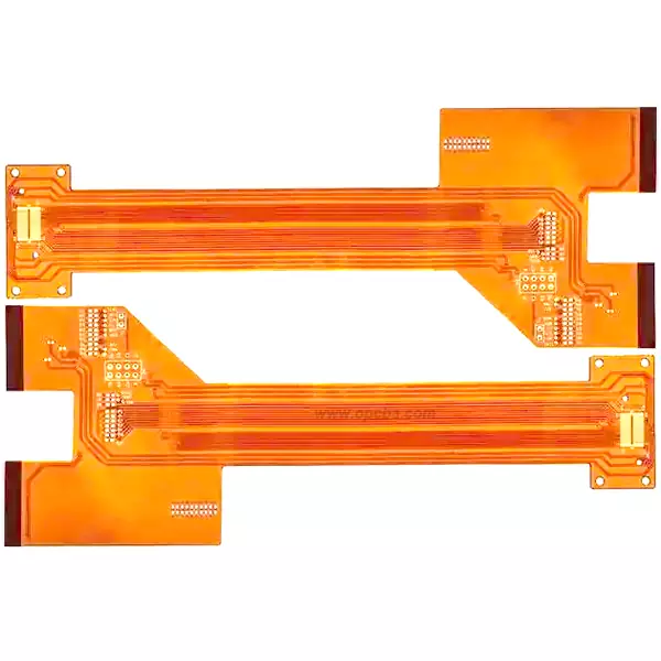
FPC Flexible Circuit Board: Thin, Bendable, and Built for Tight Spaces
A rigid PCB stops where the fold begins. In wearable devices, foldable phones, and compact medical sensors, the board itself has to bend—sometimes once during assembly, sometimes millions of times over the product’s life. An FPC flexible circuit is the answer to that mechanical constraint. It replaces static fiberglass with a thin polymer film that can flex, fold, and conform to the shape of the enclosure.
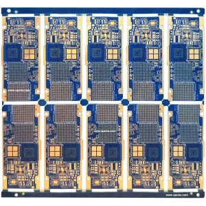
We fabricate flexible PCB products on both polyimide and polyester base films, from single-sided circuits to 8-layer multilayer boards. The material choice, layer count, and coverlay configuration are driven by one question: what does this board need to survive?
Material: PI vs. PET — One Choice, Two Different Products
The substrate decision splits FPC board designs into two paths.
Polyimide (PI) is the industry standard for any application that involves soldering, heat, or repeated flexing. It handles reflow temperatures above 280°C without softening, resists tearing through millions of bend cycles, and remains stable in high-vibration environments. Automotive sensors, medical implant connectors, and smartphone display flexes use PI because there is no room for substrate failure.
Polyester (PET) costs less and is inherently more transparent. The trade-off is thermal: PET softens around 80°C, which rules out standard lead-free reflow. Components are attached with low-temperature solder or conductive adhesive. For a disposable medical patch, a static LED light strip, or a low-cost consumer sensor that never sees heat, PET does the job at a fraction of the material cost.
I’ve seen a design team default to PI for a simple battery flex that sat at room temperature and never moved. They paid a premium for thermal performance they never used. The right material isn’t always the higher-spec one.
What You Can Specify
Our standard FPC flexible circuit capability spans the following range:
-
Board thickness: 0.05 mm to 0.4 mm. The extreme thin end—50 μm—is used in applications where the flex circuit must fold into a radius smaller than 1 mm or sit flush under a component with zero mechanical clearance. For more details on compact lightweight FPC production techniques, refer to our article: FPC Fabrication with Small Size and Lightweight At this gauge, handling during assembly requires fixturing; the board will not support its own weight.
-
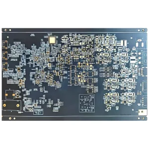
Layer count: 1 to 8 layers. Single-layer and double-layer designs cover most dynamic flex applications. Multilayer stacks above four layers are typically used in rigid-flex assemblies where the flex section carries dense signal routing between rigid zones. We can build up to eight layers with plated through-holes or blind vias as the design requires.
-
Copper weight: 0.5 oz to 2 oz. Half-ounce copper is standard for high-density, fine-pitch flex with 2 mil traces. Two-ounce copper is used when the flex carries power or when lower IR drop is needed across longer trace lengths. The trade-off is bend radius: heavier copper increases the minimum safe bend radius, so dynamic flexes tend to stay at 0.5 oz or 1 oz.
-
Minimum trace/space: 2 mil. This is the capability floor. At 2 mil, trace width variation during etching becomes a significant factor in impedance control. If your design pushes this limit, expect tighter DFM feedback and possibly higher scrap rates on the first run.
-
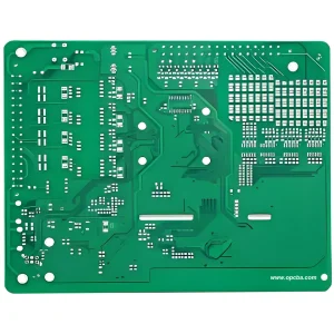
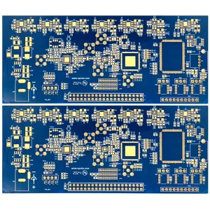
Coverlay (solder mask): Yellow, black, green. Yellow is the natural color of polyimide coverlay and remains the default for most flexible PCB designs—it provides the best balance of flexibility, adhesion, and cost. Black coverlay is chosen for cosmetic reasons, such as when the flex is visible through a transparent housing. Green is available for designs that want visual consistency with rigid board sections.
-
Silk screen: White or black, selected for contrast against the coverlay.
-
Surface finish: OSP, immersion gold (ENIG), or immersion silver. ENIG is the standard choice for fine-pitch SMT pads on FPC board products—it provides a flat, solderable surface that holds up through multiple thermal cycles. Immersion silver offers similar planarity at a lower cost. OSP is used when cost is the dominant factor, with the understanding that shelf life is limited.
Design Considerations for Flex
Bend radius. A static bend—where the flex is formed once during assembly and never moves again—can be as tight as 6× the total board thickness for single-layer designs. Dynamic flexing applications, such as a printer head cable or a flip-phone hinge, need a minimum bend radius of 15× to 20× board thickness to achieve the required cycle life. Routing traces perpendicular to the bend axis rather than parallel to it prevents stress cracks from propagating along the copper.
Stiffeners. Polyimide stiffeners are applied in the connector and component mounting areas to provide mechanical support. The thickness of the stiffener is matched to the connector’s insertion force requirements. Without a stiffener, repeated insertion cycles will delaminate the flex at the connector pads.
Copper balancing. Uneven copper distribution across the layers of a multilayer flex can cause the board to curl after lamination. We add non-functional copper fills to balance the pattern and keep the board flat. This is not cosmetic; curl directly affects SMT placement accuracy.
Applications
Our FPC flexible circuit products are used in wearable devices where the board conforms to a wrist or body contour, mobile phones where display and battery connections fold into the enclosure, automotive electronics where the flex survives engine-bay temperatures and vibration, and medical equipment where biocompatibility and sterilization tolerance are required. If the board needs to bend, fold, or fit where a rigid PCB cannot, flexible PCB technology is the starting point.
Ordering
This is a custom product. Every FPC board we build is different—your material choice, layer stack, stiffener requirements, and bend specifications define the design.
To get a quotation, send your Gerber file to sales@opcba.com. Include your preferred substrate material, coverlay color, surface finish, stiffener requirements, and target quantity. We’ll return a formal quote with a lead time as soon as the engineering review is complete.