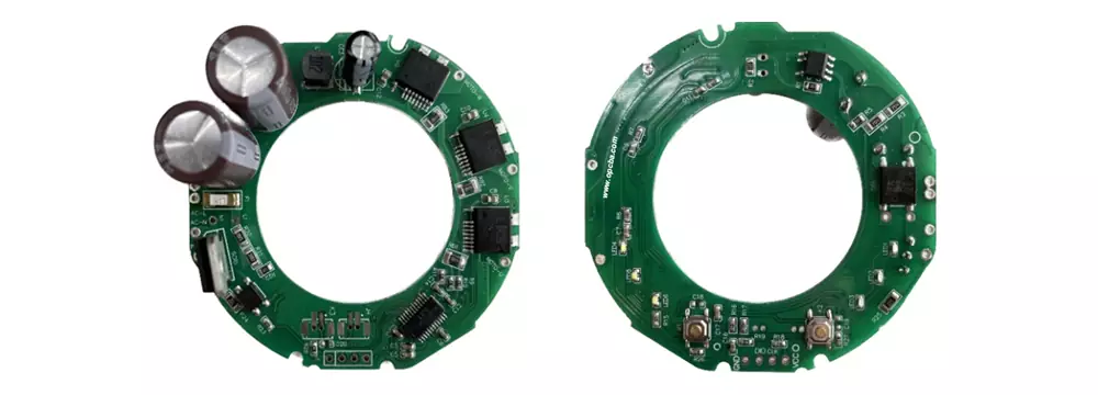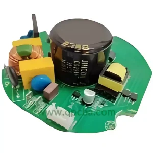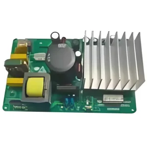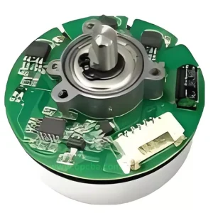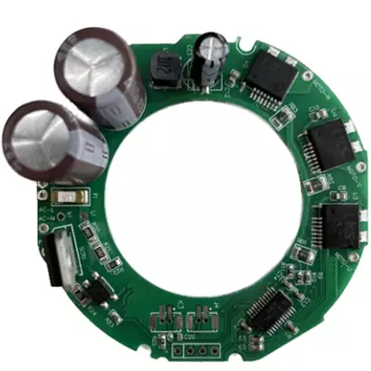
Designing a Home Hair Dryer that spins at 110,000 RPM while heating air to the right temperature isn’t just a motor challenge—it’s a board-level integration problem. The more external components you add, the larger the PCB grows, and the harder it becomes to fit everything into a slim, handheld enclosure. This type of compact, high-reliability design is a key focus of our Smart Home PCBA solutions.
This hair dryer controller solves that problem at the chip level. Built around a motor-control-dedicated MCU, it integrates the operational amplifier, comparator, DAC, and MCPWM peripherals that would otherwise require separate ICs. Fewer external parts. Smaller board. Faster time to market.
What This Controller Brings to Your Hair Dryer Design
The MCU at the center of this hair dryer PCBA is designed for single-motor applications where space is tight and reliability is non-negotiable. Here’s what it packs and why each feature matters in a hair dryer context.
Integrated 5V LDO. The MCU includes a built-in 5V low-dropout regulator, so you don’t need an external LDO to power the logic side. For a 120W motor and 1400W heating element running off rectified mains, every saved component reduces board area and BOM line items.
Built-in high-speed comparators and DAC. Overcurrent and overvoltage protection are handled inside the chip. The DAC sets a precise threshold; the comparator triggers a fault shutdown when the current sense voltage exceeds that threshold. The negative terminal voltage reference is selectable, which means the same comparator can monitor both positive and negative current swings without additional level-shifting circuitry.
Instrument-grade fully differential programmable gain amplifier. This op-amp stage accepts the shunt resistor’s differential signal directly—no DC bias needed. It handles positive and negative current signals cleanly, which matters because the motor phase current reverses direction during commutation. The 0.5% voltage reference built into the chip keeps ADC readings accurate across the full temperature range.
Industrial temperature range. The MCU is rated for 105°C ambient operation. In a hair dryer handle where the heating element sits centimeters from the control board, that margin makes a difference.
Performance Numbers That Match the Application
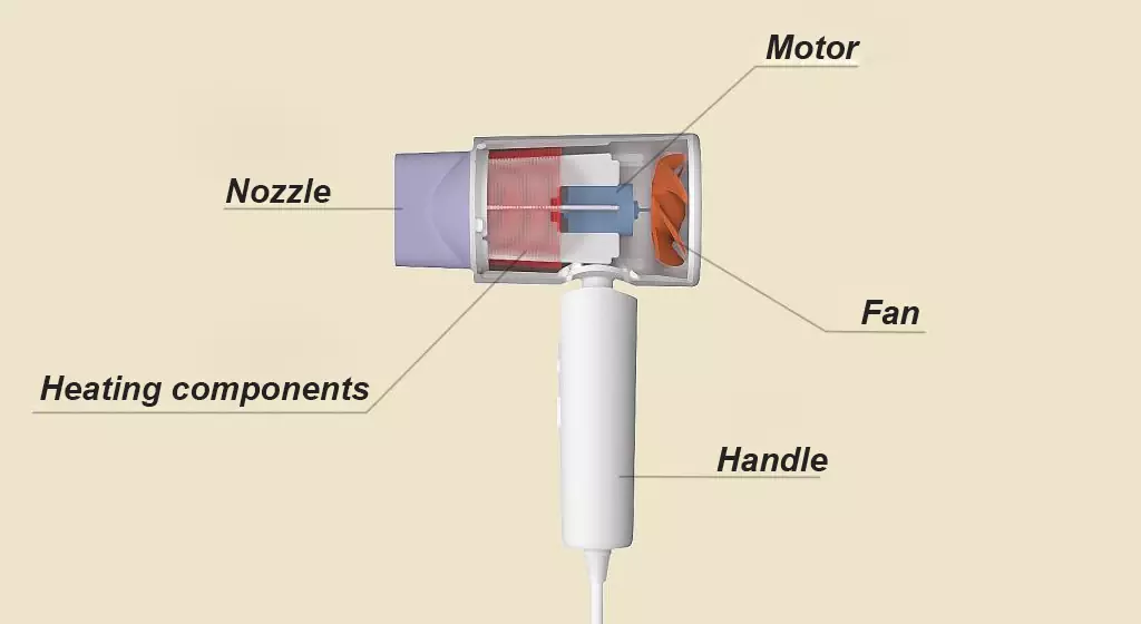
The two-pole-pair motor in a typical high-speed Home Hair Dryer runs at 110,000 RPM—that’s an electrical frequency around 3.67 kHz. The MCU’s PWM module switches at 28 kHz, well above the audible range, so there’s no whine from the stator. At 120W motor power and 1400W heating, the controller manages both paths without external gate drivers or auxiliary supplies.
For designers pushing toward 220,000 electrical RPM—equivalent to a two-pole motor at that mechanical speed—the compute headroom is already there. With the current two-pole-pair design at 110,000 RPM, the electrical frequency stays at just 3.67 kHz, leaving plenty of margin for more demanding motor configurations.
Two Configurations, One Platform
The same hair dryer PCBA supports both standard and negative-ion models.
In a standard configuration, the MCU drives the BLDC motor via six PWM channels, monitors the DC bus current through the integrated op-amp, and toggles the heating element based on the user-selected mode. Temperature feedback is optional—the heating wire runs at a fixed power level calibrated during development.
For a negative-ion Home Hair Dryer, a high-voltage generator module connects to a dedicated output pin on the controller. The MCU enables or disables the ionizer based on the operating mode, and the generator’s DC supply is derived from the main power rail with minimal additional circuitry.
The algorithm side includes vibration noise suppression and phase current smoothing compensation. In practice, this reduces the tonal noise that comes from commutation ripple and keeps the motor torque smooth even as the load changes when the user blocks or unblocks the air inlet.
Simplified BOM Reference
Here’s a condensed reference BOM for the core control section of this hair dryer controller. Values are indicative and depend on your exact enclosure and thermal requirements.
| Item | Suggested Value / Spec |
|---|---|
| Main MCU | Motor-dedicated MCU with built-in op-amp, comparator, DAC, MCPWM, 5V LDO |
| Power MOSFETs (6x) | 600V / 10A N-channel, TO-252 or DFN package |
| Gate driver (optional) | Integrated into MCU or external half-bridge driver depending on MOSFET Qg |
| Shunt resistor | 0.05Ω / 2W, 1% tolerance, for phase current sensing |
| DC bus capacitor | 450V / 100μF electrolytic + 1μF ceramic in parallel |
| Buck converter (if needed) | AC/DC offline buck to supply MCU VIN if not using external LDO |
| Heating element | 1400W nichrome wire assembly, switched via TRIAC or relay |
| Negative ion generator (optional) | 6kV output module, 12V DC input |
| NTC thermistor (optional) | 100kΩ at 25°C, placed near heating element for overtemperature protection |
This BOM eliminates the external LDO, external op-amp, external comparator, and external voltage reference that a generic MCU would require. The net saving is typically 4 to 6 passives and 2 to 3 ICs, which translates to a smaller PCB and a faster SMT cycle. For more details on the standard manufacturing flow for these types of boards, including compliance requirements, see our guide: Lead-Free PCBA Processing: Step-by-Step Guide.
Getting Started
If you’re evaluating hair dryer PCBA solutions or need a reference design to accelerate your next Home Hair Dryer project, we can provide schematics, layout guidelines, and a pre-programmed MCU sample. Reach out at sales@opcba.com with your target specifications, and we’ll put together a package that matches your motor and heating configuration.