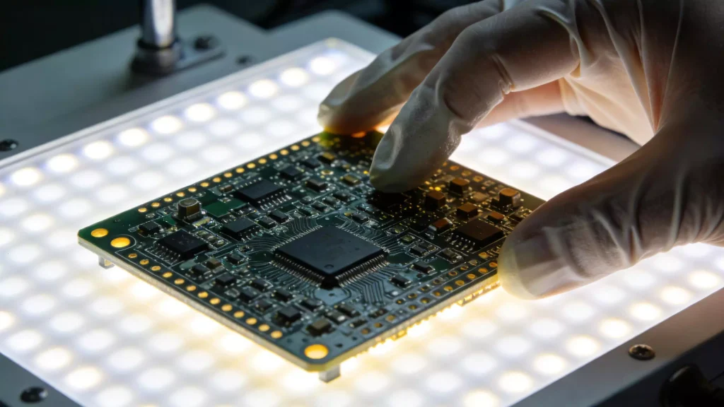
Surface Mount Device (SMD) welding is a critical skill in modern electronics assembly, used to attach compact components to printed circuit boards (PCBs). Unlike traditional through-hole welding, SMD welding requires precision tools and tailored processes to handle small, delicate components. This comprehensive guide breaks down SMD welding techniques, process types, equipment, and selection criteria to help you achieve reliable, high-quality results—whether for prototyping, repair, or mass production.

SMD Welding vs. Through-Hole Welding: Key Differences
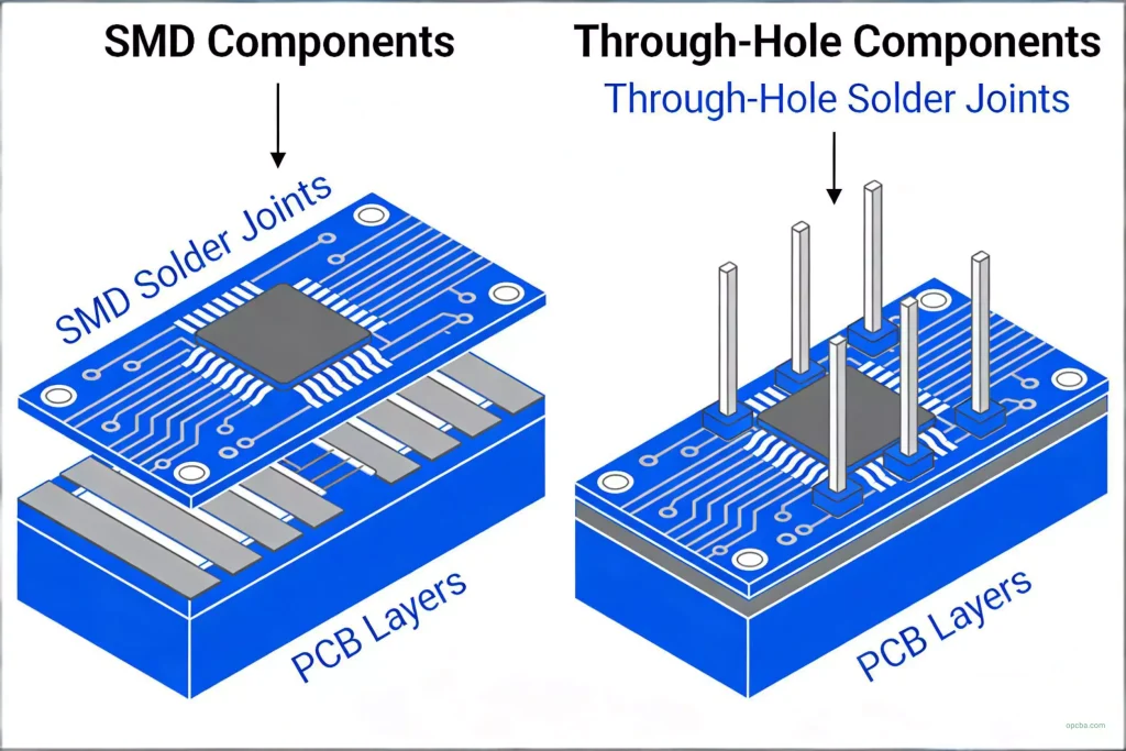
SMD welding and desoldering share core principles with through-hole welding, but differ in execution due to component size and mounting style. Through-hole components have leads inserted into PCB holes, while SMD components sit directly on the PCB surface. This distinction impacts tooling:
- SMD Desoldering: Typically uses a hot air blower to heat the component and solder joints evenly, allowing safe removal without damaging the PCB or component.
- SMD Welding: Can be completed with a soldering iron and solder wire for small-scale work, or solder paste/solder balls (for BGA components) paired with hot air repair benches or reflow equipment for precision.
Common SMD Welding Process Types
All SMD welding processes have unique technical challenges, but proven solutions exist to mitigate risks. The choice of process depends on yield requirements, cost, and application specificity. Below are the most widely used methods:
1. Convection-Dominated Infrared (IR) Reflow Welding
Convection IR welding has emerged as the preferred SMD welding process for most manufacturing scenarios. By combining infrared heat with forced air circulation, it delivers uniform temperature distribution across the PCB. This uniformity boosts yield rates by reducing solder defects (e.g., cold joints, component damage) and lowers long-term operating costs compared to other methods. It is ideal for high-volume production of consumer electronics, automotive PCBs, and industrial devices.
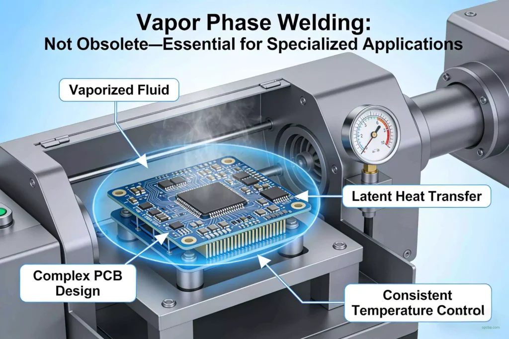
2. Vapor Phase Welding
Vapor phase welding is not obsolete—it remains essential for specialized applications. This process uses the latent heat of vaporized fluid to heat components, ensuring consistent temperature control even for complex PCB designs (e.g., multi-layer boards, components with varying thermal masses). It is commonly used in aerospace, medical device manufacturing, and other industries where precision and reliability are non-negotiable.
3. Supplementary Reflow Processes
For niche professional applications, specialized reflow processes complement infrared and vapor phase methods (rather than replacing them):
- Laser Welding: Offers pinpoint heat application, making it suitable for micro-components, high-density PCBs, and applications where minimal thermal impact is critical (e.g., sensor assemblies).
- Hot Rod Resistance Welding: Used for selective soldering of specific joints, ideal for low-volume, high-precision tasks or repairs on sensitive components.
The final process selection must align with application requirements, solder defect history, and total cost of ownership (including equipment, materials, and labor).
SMD Welding Processes for Mass Production vs. Manual Work
Mass Production: SMT Machines & Reflow Furnaces
Factory-scale batch production relies on Surface Mount Technology (SMT) machines, with reflow furnaces as the primary equipment. Reflow furnaces automate the welding process by heating PCBs with pre-applied solder paste to a precise temperature profile, melting the solder and forming strong joints as it cools. The two most widely used reflow processes in electronics manufacturing are:
- Vapor phase reflow (for high-reliability, complex assemblies)
- Infrared convection reflow (for high-volume, cost-effective production)
Manual SMD Welding: Repair & Prototyping
Manual SMD welding is reserved for repair, rework, or small-batch prototyping. The essential tools include: a temperature-controlled soldering iron/soldering station, hot air SMD repair bench, high-quality solder wire, and solder paste. This process requires skill to avoid overheating components (e.g., microchips, resistors) and ensure consistent joint quality. It is critical for electronics repair shops, hobbyists, and R&D teams.
How to Select the Right SMD Welding Process
The electronics industry continues to use mixed PCB assembly—combining SMD components and through-hole components—so through-hole welding will remain relevant for the foreseeable future. When selecting an SMD welding process, consider the following factors:
Component & Assembly Type
For through-hole active and passive components, wave soldering remains the most cost-effective method. For SMD-dominant assemblies, solder paste reflow is often preferred. Mixed assemblies may require a combination of processes (e.g., reflow for SMDs, wave soldering for through-hole components).
The Role of Nitrogen in Welding
Nitrogen is widely used in wave soldering and reflow processes, especially with low-solid-content or no-clean fluxes. It reduces oxidation during welding, improving joint appearance and reliability. However, nitrogen is not a solution for all solder defects—it only marginally impacts output and cannot fix issues related to PCB design, flux activity, solder paste quality, printing accuracy, or temperature profiling. Use nitrogen strategically, not as a “panacea.”
Final Selection Criteria
The optimal welding process depends on the mix of electronic components, production volume, reliability requirements, and budget. No single process replaces others—they complement each other. Even manual welding will remain essential for specialized tasks. Always test processes with your specific PCB design and components to validate yield and defect rates.
PCB Assembly (PCBA) Process Flow Overview
SMD welding is a key step in the broader PCBA process. The full workflow typically includes: PCB design & fabrication → solder paste printing → SMD component placement → reflow welding → through-hole component insertion (if mixed assembly) → wave soldering → inspection & quality control → rework/repair (if needed) → final assembly. Each step impacts welding quality, so end-to-end process control is critical.
FAQs About SMD Welding
Q: Can I use the same solder for SMD and through-hole welding?
A: While some solders (e.g., Sn63/Pb37) work for both, SMD welding often requires finer solder wire (0.3–0.5mm) or solder paste to accommodate small components. Choose solder with a melting point compatible with your components.
Q: How do I avoid SMD welding defects?
A: Ensure proper temperature profiling, use high-quality flux/solder paste, maintain clean PCB surfaces, and invest in precision tools. For mass production, automate placement and welding to reduce human error.
Q: Is infrared or vapor phase welding better for SMDs?
A: Infrared convection is better for high-volume, cost-sensitive production. Vapor phase is superior for complex, high-reliability assemblies where temperature uniformity is critical.