Electronic components are the foundational building blocks of Printed Circuit Board(PCB) circuits.. They control current flow, transmit signals, and convert energy in all electronic devices. As the core of electronic systems, Electronic Components are indispensable for the normal operation of every electronic product. This guide details the core functions, standard circuit codes, quality testing methods, and key specifications of essential electronic components—from resistors and capacitors to triodes and thyristors. Mastering these details is critical for reliable PCB design, PCB Assembly(PCBA), and troubleshooting, assembly, and troubleshooting, as these components directly determine the performance and stability of the entire circuit.
1. Electronic Components: Resistor | Code: R
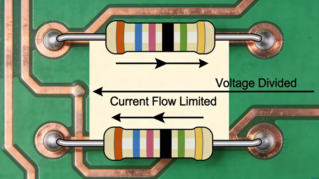
A resistor, one of the most basic Electronic Components, blocks electric current in a circuit. It limits the current passing through its connected branch and is widely used in various electronic devices due to its simple structure and stable performance.
Core Functions
- Current limiting and voltage division
- Voltage reduction and circuit isolation
- Current diversion and signal offset
Quality Testing
Use a multimeter’s resistance range: a good resistor matches its nominal value (or falls within the allowable error range). Burnt resistors appear black and fail resistance tests. In-circuit measured resistance ≤ the nominal value is normal. This testing method is applicable to most passive Electronic Components with resistance characteristics.
Unit
Ohm (Ω), Kiloohm (KΩ), Megaohm (MΩ)

2. Electronic Components: Capacitor | Code: C
A capacitor is another essential type of Electronic Components that stores and releases electric charge (capacitance). It has two types: polar and non-polar. For new polar capacitors, the long pin is the positive pole; the short pin is the negative pole. As a key energy storage component among Electronic Components, it plays an irreplaceable role in circuit stability.
Key Characteristics
Blocks DC current, allows AC current to pass.
Core Functions
- Circuit isolation and signal coupling
- Bypass and noise filtering
- Tuning, energy conversion, and control circuit regulation
Quality Testing
Short-circuit the two poles for discharge first. Measure resistance with a multimeter:
- Good: Needle swings out and returns to its original position.
- Short circuit: Needle swings out and does not return.
- Leakage: Needle cannot fully return to its original position after swinging.
- Open circuit: Needle does not swing at all.
For small capacitors (no needle swing), use the series “test pen method” or “AC signal method” for testing. This is a common testing technique for capacitive Electronic Components.
Key Specs & Structure
Structure: Two metal films with lead pins, separated by an insulating dielectric material.
Withstand voltage (V): Maximum long-term operating voltage; when replacing, capacitance should match the original, and withstand voltage ≥ 1.414× the power supply voltage.
Capacity: Represents charge storage capacity; capacitive reactance $$X_C=1/(2\pi fC)$$ (f = AC signal frequency, C = capacitance). (Corrected the missing parameter “C” in the original formula)
3. Electronic Components: Inductor | Code: L
An inductor is a magnetic energy storage type of Electronic Components, made by winding insulated wire around an insulating skeleton. Some add magnetic/iron cores to enhance inductance when energized. It converts electrical energy into magnetic energy for storage (also called a choke or reactor), and is often used in conjunction with capacitors among Electronic Components to form oscillation circuits.
Key Characteristics
Allows DC current to pass (small voltage drop, low conductor resistance); blocks AC current. Higher AC frequency leads to greater coil impedance.
Core Functions
- Filtering, voltage boosting, and resonance
- Frequency division
- Forms series/parallel oscillation circuits with capacitors
Quality Testing
Use a multimeter’s resistance range: a good inductor has a measurable resistance (no short circuit). Burnt inductors appear black and fail tests. Similar to resistors, this is a basic testing method for inductive Electronic Components.
Unit
Henry (H), Millihenry (mH), Microhenry (μH)
4. Electronic Components: Power Transformer | Code: B
A power transformer is a power conversion type of Electronic Components, made by winding a primary coil and one/more secondary coils on an insulating framework with a silicon steel sheet core. It works on the principle of electromagnetic induction (electricity generates magnetism, magnetism generates electricity) to convert alternating current (AC). As a key power supply component among Electronic Components, it is widely used in power supply circuits.
Core Working Principle
- AC input to the primary coil generates a changing magnetic field.
- The changing magnetic field passes through the secondary coil to produce a changing AC output.
Core Formulas & Classification
Turns ratio formula: $$N_1/N_2=V_1/V_2$$ (V1 = input voltage, V2 = output voltage, N1 = primary coil turns, N2 = secondary coil turns). (Corrected the missing parameter “V2” in the original formula)
Classification:
- Step-down transformer: $$N_1>N_2, V_1>V_2$$ (Corrected the missing parameter “V2” in the original formula)
- Step-up transformer: $$N_1 (Corrected the incomplete expression in the original formula)
Power Characteristic
Ideal transformer: input power = output power ($$P_1=P_2$$, i.e., $$I_1V_1=I_2V_2$$); (Corrected the incomplete formula in the original text) actual transformer: output power is 70–90% of input power.
5. Electronic Components: Diode | Code: D or BG
A diode is a semiconductor type of Electronic Components made of a PN junction, with positive and negative poles (P = positive, N = negative). There are common types: zener, varactor, LED, switching, and photodiodes. As a unidirectional conduction component among Electronic Components, it is widely used in rectification and voltage stabilization circuits.
Key Characteristic
Unidirectional conduction (current flows only from positive to negative pole).
Core Functions
Rectification, voltage stabilization, varactor tuning, light emission, switching, voltage boosting.
General Quality Testing & Electrode Discrimination
Testing: Use multimeter R×1K gear; good diode has forward resistance 3–9KΩ and reverse resistance ∞ (infinite).
Electrode discrimination: When forward resistance is 3–9KΩ, the black probe connects to the positive pole, red to the negative pole (marked black/white end = negative pole on the case). This discrimination method is suitable for most diode-type Electronic Components.
Special Diode Types & Features
Zener Diode
Functions as a voltage stabilizer; wired in reverse (negative pole to positive voltage, positive pole to negative voltage). When reverse voltage exceeds the zener value, it conducts and limits the negative pole voltage to the zener value. It is a special voltage-stabilizing type among Electronic Components.
Light-Emitting Diode (LED)
Converts electrical energy to light; has unidirectional conduction (reverse breakdown voltage ≈5V). Must be in series with a current-limiting resistor: $$R=(E-UF)/IF$$ (E = power supply voltage, UF = LED forward voltage drop, IF = LED working current). Low-voltage power supply (6–24V); 80% lower energy consumption than incandescent lamps (100,000-hour use, light attenuation to 50% of initial value). It is a light-emitting type among Electronic Components.
Photodiode
Converts optical signals to electrical signals (not a rectifier); has unidirectional conduction like a common diode. It is a photoelectric conversion type among Electronic Components.
Bidirectional Trigger Diode
Symmetrical two-terminal semiconductor; triggers bidirectional thyristors, used for over-voltage protection, timing, phase shifting, dimming. Testing: Good diode has infinite forward and reverse resistance; low/0 resistance means breakdown. It is a trigger-type among Electronic Components.
6. Electronic Components: Unidirectional Thyristor | Code: BCR
A unidirectional thyristor (crystal thyratron) is a controllable semiconductor type of Electronic Components, with a four-layer, three-terminal structure and three PN junctions (PNPN). Unlike diodes, its forward conduction is controlled by the gate electrode current (no current amplification for the gate). It is a key controllable component among Electronic Components.
Core Functions
Rectification, voltage stabilization, circuit switching.
Quality Testing & Electrode Discrimination
Testing: Use multimeter R×1K gear; good thyristor has ∞ resistance for AK/AG (forward/reverse), 3–9KΩ forward resistance for GK, and ∞ reverse resistance for GK.
Electrode discrimination: When GK forward resistance is 3–9KΩ, black probe = G (gate), red probe = K (cathode), the remaining pin = A (anode).
Working Principle
- Conduction conditions: Positive voltage between A and K + positive voltage on G (both required).
- Latching: Once on, the thyristor remains conductive even if G voltage is removed/reduced.
- Turn-off condition: Reduce/remove A-K forward voltage to make anode current less than the minimum holding current.
7. Electronic Components: Bidirectional Thyristor | Code: SCR
A bidirectional thyristor is a bidirectional controllable type of Electronic Components that conducts in both directions. It is essentially two reverse-parallel unidirectional thyristors—a five-layer (NPNPN) semiconductor with four PN junctions and three electrodes (A1, A2, G; no anode/cathode due to symmetrical N-layer main electrodes). It is widely used in AC control circuits among Electronic Components.
Key Limitation
Low voltage rise rate tolerance (carriers do not return to cut-off position after one-way conduction; protective measures required).
Core Functions
AC circuit control (temperature control, dimming, explosion-proof AC switches, AC motor speed regulation, commutation, AC voltage stabilization).
Quality Testing & Electrode Discrimination
Testing: Use multimeter R×1/R×10 gear; ∞ resistance for T2-T1/T2-G (forward/reverse); tens to hundreds of ohms for T1-G (forward/reverse).
Electrode discrimination: When T1-G has a slightly higher resistance, red probe = G, black probe = T1, the remaining pin = T2.
8. Electronic Components: Triode | Code: BG or Q, V, T
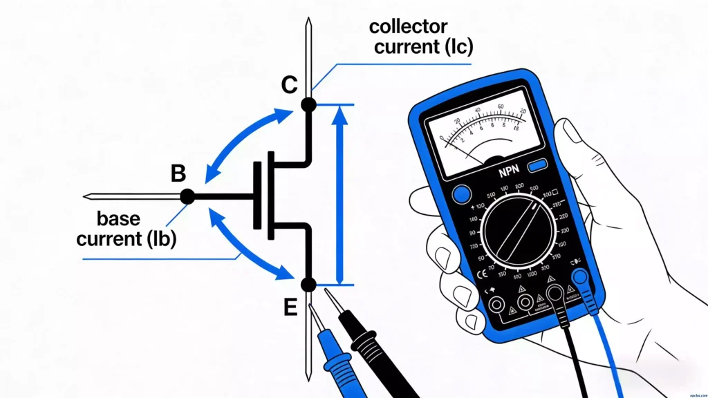
A triode (transistor) is an amplifying semiconductor type of Electronic Components, with two PN junctions and three electrodes: base (B), collector (C), emitter (E). Classifications: PNP/NPN (conductive type); high/medium/low power (power rating); high/low frequency (application). It amplifies small currents to control large currents, with current amplification coefficient increasing with temperature. As a core amplifying component among Electronic Components, it is the foundation of signal amplification circuits.
Core Functions
Current/voltage amplification, voltage stabilization, switching, oscillation.
Electrode Discrimination (Multimeter R×1K/R×10K Gear)
- Base (B): Fix one probe to a pin; measure the other two. If both resistances are low (3–9KΩ), the fixed pin = B.
- Conductive type: Red probe fixed to B = PNP; black probe fixed to B = NPN.
- Emitter (E) & Collector (C): Use R×10K gear to measure the two non-base pins. The smaller resistance (≥30KΩ) indicates:
- PNP: Red probe = E (“small red E”); remaining pin = C.
- NPN: Black probe = E (“small black E”); remaining pin = C.
Quality Testing
A good triode meets both criteria:
- B-C/B-E (forward/reverse): 3–9KΩ forward resistance, ∞ reverse resistance.
- C-E (forward/reverse): ≥30KΩ forward resistance, ∞ reverse resistance.