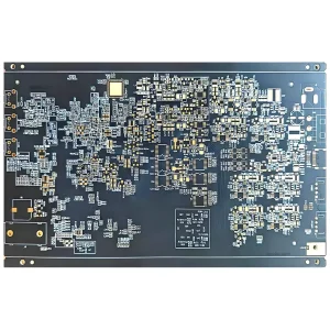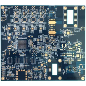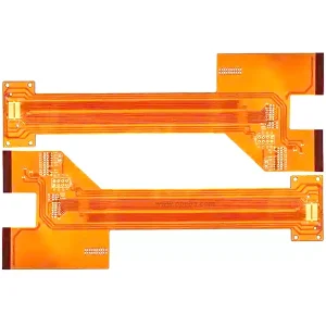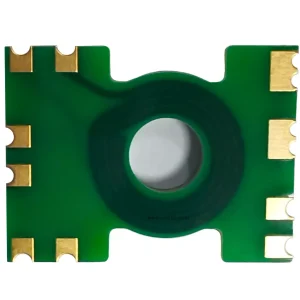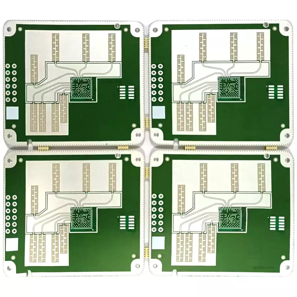
Millimeter-wave radar PCB is where the sensing chain either holds together or falls apart. At 24 GHz and above, trace geometry, substrate loss and layer alignment all translate straight into detection range. This page covers what we build, which substrates we process, and where the manufacturing limits sit.
What We Build
We produce millimeter-wave radar boards for automotive, industrial and security applications, from prototype quantities through volume production. Boards are fabricated to IPC-6012 with impedance testing and material certificates for every batch, then assembled to IPC-A-610 with process control written specifically for fine-pitch radar devices.
Because the RF section and the digital section make different demands on the same board, most millimeter-wave designs need more layers than a digital-only board of the same size. The extra layers are usually ground and power planes that give the RF traces a clean reference and keep switching noise away from the receive path.
Substrate Selection for Millimeter-Wave Radar
Substrate choice sets the loss floor. The four laminates below cover most millimeter-wave work, and the deciding number is the dissipation factor: at these wavelengths, a lower Df means measurably less attenuation across the trace run.
| Laminate | Dielectric constant (Dk) | Dissipation factor (Df) | Where it fits |
|---|---|---|---|
| RO4350B | 3.48 | 0.0037 | Cost-sensitive high-frequency work and mixed FR-4 stacks |
| RO3003 | 3.00 | 0.0013 | RF front ends where the loss budget is tight |
| Astra MT77 | 3.00 | 0.0017 | Automotive radar across a wide temperature range |
| Taconic RF-35 | 3.5 | 0.0018 | FMCW and Doppler radar designs |
Two practical notes on the table. First, Dk and Df are typical values; confirm against the current datasheet revision before you commit a stackup. Second, the thickness of the laminate matters as much as the grade, because it sets the trace width you need for a given impedance.
Stackup and Process for Radar Boards
Mixed builds are the norm. A low-loss laminate carries the antenna and RF layers, while FR-4 handles the digital and power sections, which keeps cost down without putting loss into the signal path. The difficulty concentrates in lamination: the two materials do not flow the same way under heat and pressure, so parameters that suit one will distort the other.
Beyond the stackup, three process points decide whether the design arrives intact. Impedance has to be verified rather than assumed, which is why we test coupons from every batch. Via quality matters more than usual because a stub on a 77 GHz path costs phase accuracy, so blind and buried vias are used where the design calls for them. And layer-to-layer registration has to hold, because an antenna array only works if every element sits where the artwork put it. The broader design context sits in our guide to hybrid stackups and in the radar PCB capability overview.
FAQ
How is a millimeter-wave radar board different from a standard high-frequency PCB?
Three things. The frequency is higher, so loss and phase accuracy matter more. The antenna is usually on the board itself rather than a connector, which makes substrate uniformity and registration critical. And the digital side is close by, so the stackup has to separate RF from high-speed switching without giving up board area.
Which laminate should I pick for 77 GHz?
It depends on the loss budget and the temperature range. RO3003 gives the lowest dissipation factor of the four above, which suits a tight loss budget. Astra MT77 trades a little loss for stability across a wide temperature range, which is why it turns up in automotive radar. RO4350B is the cost-effective option when the trace runs are short or the stack mixes FR-4.
Can you support both prototypes and volume production?
Yes, on the same process. Prototype batches run through the same impedance testing and material certification as production batches, because the failure mode that hurts most is a design that passes in the lab and drifts in the field. For millimeter-wave sensors, millimeter-wave sensing modules usually go through a first-article review before volume release.