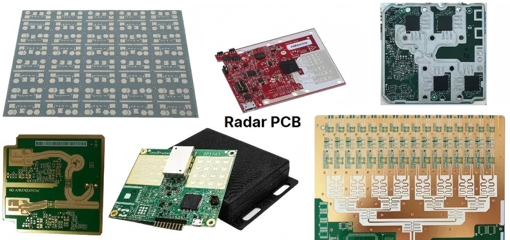
Radar PCBs are the boards behind technologies like automotive sensors, weather radar, and defense systems. They transmit and receive high-frequency signals so radar systems can detect objects and measure their speed or distance. Designing radar PCBs is demanding work: it requires handling fast signals, avoiding interference, and maintaining reliability in harsh environments.
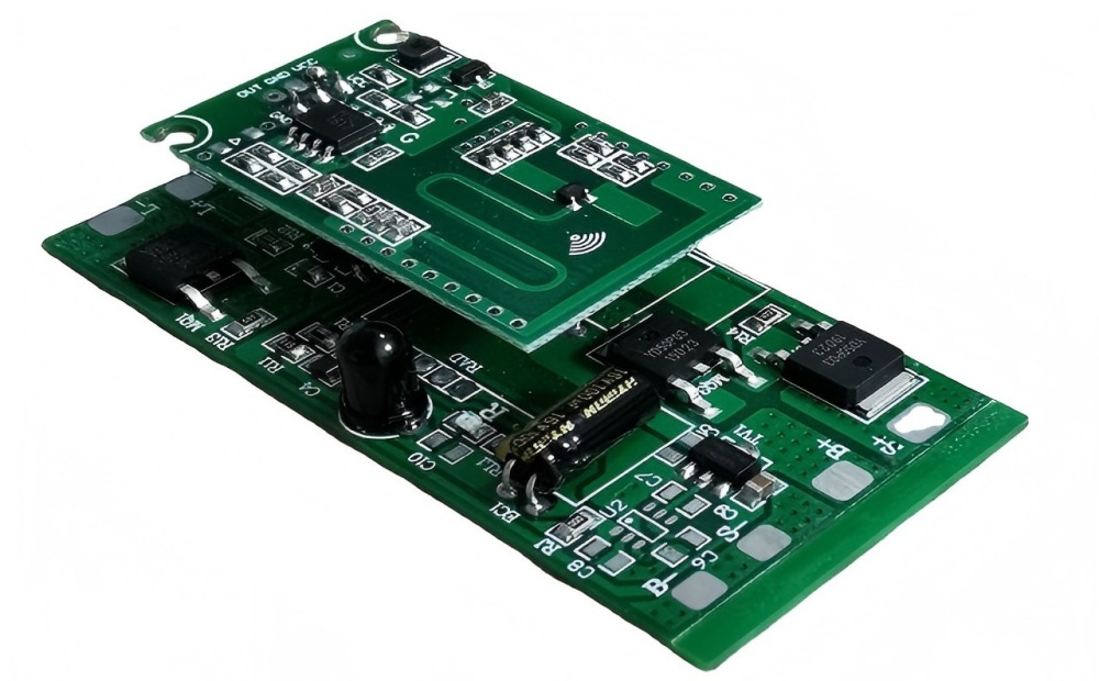
What is a Radar PCB?
Radar PCBs are printed circuit boards designed to handle extremely high-frequency signals within the 1 GHz to 77 GHz range. These boards are used in radar systems for precise object detection, ranging, and velocity calculation. Material selection, design precision, and assembly accuracy all shape their performance.
Key Specifications for Radar PCBs
1. Range: This indicates how far away an object is. The longer it takes for the signal to return, the farther the object is.
2. PRF (Pulse Repetition Frequency): This is how many times per second the radar transmits a signal. A well-chosen PRF helps the radar track fast-moving objects.
3. Minimum Range: This is the closest distance at which the radar can detect an object. If too close, the signal may measure the return too quickly.
4. Maximum Clear Range: If the radar transmits a new signal before the previous one returns, it can cause interference.
How Radar Systems Work
Radar systems operate by emitting radio signals and listening for their reflections. First, the transmitter sends signals through the antenna. When the signal encounters an object, it bounces back and is received by the receiver.
Once the radar receives the signal, the processor calculates the object’s distance, speed, and even direction by analyzing the signal’s time delay and variations.
Radar PCB Design Considerations
1. Select the correct layer stackup
RF PCBs handle both digital and radio frequency signals, which may require separate ground planes. This often means multiple dedicated ground layers, increasing the board’s layer count. The layer stack determines trace characteristics and PCB manufacturability.
2. Selecting Suitable Materials
Common materials like FR-4 cannot handle signals above 1-2 GHz. These are termed standard loss materials (technically, they can manage high frequencies if trace lengths are short enough). For high-frequency signals, the material datasheet is the place to start. Failing that, the loss tangent or dissipation factor gives a usable estimate: a lower dissipation factor indicates lower attenuation at higher frequencies.
3. Impedance and Length Matching
High-frequency signal traces, whether analog or digital, require impedance matching and length matching. Typically, RF signals use 50-ohm impedance-matched traces, and impedance control has to hold across the full trace length. Radar PCBs also transmit and receive digital signals employing differential impedance based on communication protocols. However, many digital signals in such protocols feature extremely short rise and fall times and utilize multiple channels for data transmission and reception. These signals require length matching to preserve data integrity.
4. Maintain Proper Ground Shielding
Multiple ground shielding methods are available to prevent crosstalk and electromagnetic interference, which protects signal integrity and electromagnetic compatibility (EMC). Use ground traces and vias along high-speed signal routing paths, and employ an uninterrupted ground plane beneath high-speed signals to provide a continuous return path.
Materials Used in Radar PCBs
As with all RF and microwave PCBs, PCB materials critically influence electrical, thermal, and mechanical properties, alongside cost and manufacturability. Common laminates used in radar PCBs include the four below, and our radar PCB specifications page covers the substrate options and stackups built around them:
1. RO4350B: one of the most popular high-speed materials and one of the best low-loss materials on the market, given its availability, performance, and cost. This Rogers laminate has a dielectric constant of 3.48 and a loss factor of 0.0037. Its manufacturing process is similar to FR-4, allowing for easy use in mixed-layer stacks at a lower cost.
2. RO3003: a high-performance laminate introduced by Rogers. It costs significantly more than RO4350B, and its performance is several times higher. It is an ultra-low-loss material specifically designed for RF applications. Its dielectric constant is 3.00, and its dissipation factor is 0.0013.
3. Astra MT77: a high-performance laminate engineered for RF and millimeter-wave applications. This laminate from the Isola Group is an ultra-low-loss material with stable electrical and mechanical properties across a wide temperature range. Its dielectric constant is 3.00 and its dissipation factor is 0.0017. Its broad operating temperature range makes it an ideal choice for automotive radar.
4. Taconic RF-35: a popular laminate material widely used in high-frequency applications. It is an ultra-low-loss material with a dielectric constant of 3.5 and a loss tangent of 0.0018. It is the material of choice for Frequency Modulated Continuous Wave (FMCW) radar and Doppler radar. If you are comparing substrates for a build, our millimeter-wave radar PCB page lists the substrates and stackups we hold in production.
Applications of Radar PCB
1. Automotive Industry
Radar PCBs power Advanced Driver Assistance Systems (ADAS), enabling functions such as:
a. Adaptive Cruise Control (ACC)
b. Lane Change Assist (LCA)
c. Blind Spot Detection (BSD)
d. Automatic Emergency Braking (AEB)
e. Parking Assist (PA)
By leveraging 77GHz radar, these systems achieve higher resolution, greater accuracy, and enhanced detection capabilities that are essential for modern autonomous vehicles. Radar technology underpins object recognition, motion prediction, and vehicle safety under all weather and lighting conditions. The transition from 1 GHz to 77 GHz radar sharpens vehicle systems’ ability to distinguish between near-field objects and distant targets, so one sensor covers both short-range and long-range perception.
2. Industrial Automation
a. Precise distance and object detection
b. Tank level measurement
c. Robotics and automated guided vehicles (AGVs)
Industrial automation demands high-precision sensing, which is where radar PCBs fit. For instance, 77GHz radar systems deliver the accuracy required to detect liquid levels within containers and tanks, minimizing measurement errors. These PCBs also go into autonomous robotic systems, where they support navigation and obstacle avoidance.
3. Telecommunications
Radar PCBs are integral to 5G technology and next-generation wireless communication systems. Operating at high frequencies, these PCBs support high-speed, low-latency communication with continuous data transmission and reliable connectivity. Telecom infrastructure demands radar systems capable of long-range operation with minimal signal loss, which makes these PCBs critical for network performance and reliability. Radar also shows up in touchless sensing; our induction radar PCBA page covers the 5.8 GHz and 24 GHz assemblies used for it.
Challenges in Radar PCB Design
Radar PCB design presents unique challenges requiring specialized expertise and precision to overcome:
1. Material Selection: High-frequency radar systems need advanced materials with stable dielectric properties and ultra-low loss. Rogers RO3003G2, RO4835, and ITEQ IT180 are favored for their performance, which keeps signal attenuation low and operation consistent across conditions.
2. Copper Foil Surface Roughness: Copper foil surface roughness directly impacts signal loss at millimeter-wave frequencies. Smooth copper foil reduces surface roughness, which improves signal integrity and phase accuracy.
3. Tight tolerances: High-frequency circuit boards require precise trace widths, spacing, and impedance control. Holding 4mil/4mil trace accuracy keeps the circuit operating as designed and avoids interference or signal distortion.
4. Environmental stability: Radar PCBs must maintain consistent performance under extreme conditions, including temperature fluctuations, humidity, and mechanical stress. Both material selection and process control decide whether long-term reliability holds.
Conclusion
Radar PCB design touches high-frequency signal integrity, material selection, and long-term reliability in harsh environments at the same time. With emerging trends like artificial intelligence, millimeter wave technology, and eco-friendly materials, radar PCBs now demand greater attention and expertise than ever before.