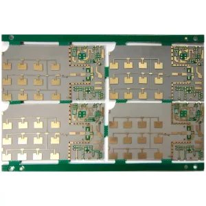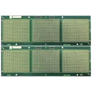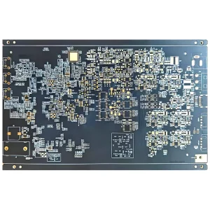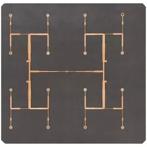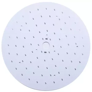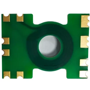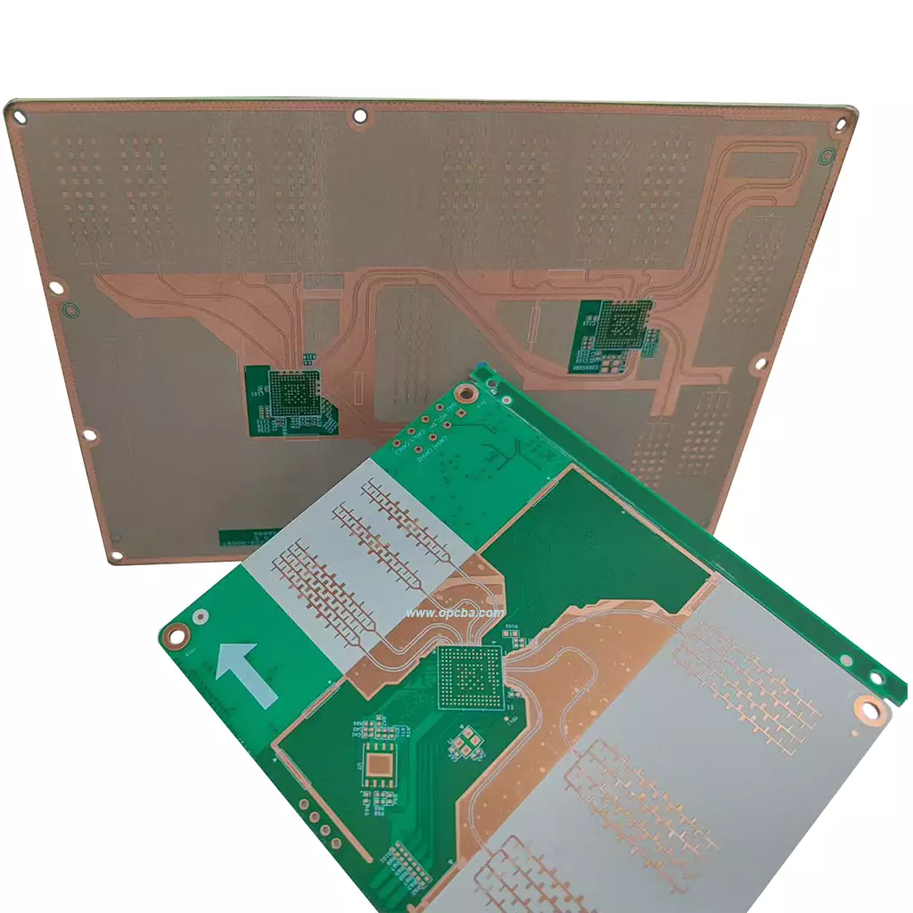
A radar PCB is built for one job: keeping high-frequency signals clean at high power, in conditions that punish ordinary boards. Low signal loss, interference rejection, heat and vibration are the four problems it has to solve before a radar system can transmit, receive and demodulate reliably.
Core Components of Radar PCB
Substrate Material: High-Frequency Adaptable Options
Substrate selection drives most of the electrical behaviour. High-frequency laminates such as PTFE and Rogers RO4350B suit millimeter-wave boards because their loss stays low at short wavelengths, while modified FR-4 balances cost and performance at lower frequencies. The wider set of options, and how they pair with stackups, is covered under radar PCB construction and materials.
Copper Foil Layer: Purity, Thickness and Functional Uses
High-purity copper foil (≥99.9%) is standard, with thickness from 1 oz to 6 oz. Thin foil lowers signal loss; thick foil raises the current-carrying capacity of the power layers.
Circuit Wiring: Impedance Matching and Precision Requirements
Radar boards use 50Ω and 75Ω impedance matching across microstrip, stripline and differential lines. Wiring precision of ±0.02 mm keeps interference down and readings stable. Impedance matching on RF traces is where most of the margin is won or lost.
Solder Pads and Hole Structure: Compatibility and Miniaturization
Lead-free solder pads match both SMT and THT processes. Blind and buried vias shrink the board outline, improve heat dissipation and support the miniaturization radar modules need.
Paint Coating: Protection and Durability Enhancement
The coating provides anti-oxidation and short-circuit protection, and an additional anti-corrosion layer extends service life in humid or chemically aggressive environments.
Civilian Applications of Radar PCB
Vehicle Radar: Autonomous Driving-Related Applications
24 GHz and 77 GHz millimeter-wave radars for advanced driver assistance use these boards for adaptive cruise control and lane departure warning, where the board has to stay small and stay reliable.
Security Radar: Outdoor and Smart Home Uses
Outdoor and smart-home installations use radar boards for human presence sensing and intrusion detection, which puts the emphasis on humidity resistance and immunity to false triggers.
Weather Radar: Civilian Weather Detection Applications
Civilian weather detection relies on stable high-frequency transmission together with heat resistance, because these installations run continuously in exposed locations.
Manufacturing Specifications
Radar boards are only as good as the process that builds them. The limits below are the ones production actually holds, and a full overview sits in our process capability list.
| Parameter | Value |
|---|---|
| Flammability rating | 94V-0 |
| Ionic contamination | At or below 1 µg/cm² |
| Copper peel strength | 7.8 N/cm |
| Through-hole copper (average / single-point minimum) | 25 µm / 20 µm |
| Blind and buried via copper (average / minimum) | 20 µm / 18 µm |
| Insulation resistance | 100 MΩ at 250 V |
Minimum trace width and spacing move with base copper thickness. Use the table as an early check on whether a design fits standard production or needs a controlled-impedance review.
| Base copper | Min outer line / space (mil) | Min inner line / space (mil) |
|---|---|---|
| 12-18 µm | 3.0 / 3.0 | 3.0 / 3.0 |
| 35 µm | 4.5 / 3.5 | 3.0 / 3.5 |
| 70 µm | 6.0 / 5.0 | 4.0 / 4.0 |
| 105-140 µm | 8.0-9.0 / 6.0-7.0 | 5.0-7.0 / 5.0-7.0 |
FAQ
What materials are used for a radar PCB?
Low-loss laminates dominate. PTFE and Rogers RO4350B are the common choices for millimeter-wave work, with modified FR-4 used where the frequency is lower and cost matters more. The deciding figure is the dissipation factor: lower values mean less attenuation at high frequency.
Can you build mixed Rogers and FR-4 stackups?
Yes. Radar boards frequently combine a low-loss laminate on the antenna and RF layers with FR-4 for the digital and power sections, because the two halves have different electrical and cost requirements. The practical constraint is the press schedule, since the two materials do not flow the same way under lamination.
What trace width and spacing can you hold on radar boards?
It depends on base copper. With 12-18 µm foil we hold 3.0 mil line and space on both outer and inner layers; at 35 µm it is 4.5 / 3.5 mil on the outer layers. Tight traces on thick copper are the limiting case, so send the stackup early if the design pushes that corner.