In PCBA (Printed Circuit Board Assembly) processing, the crystal oscillator acts as the circuit’s core “heartbeat.” When it fails, the entire system often shuts down completely. Among all failure modes, burnout stands as the most severe and hard-to-solve issue. This article dives deep into the root causes of crystal oscillator burnout and shares practical prevention steps. Whether you’re an electronic engineer, a purchaser, or a PCBA factory technician, this guide will help you avoid this high-risk problem.
Important Note: Before we start analyzing, let’s clarify a key concept: crystal oscillators fall into two main types—passive and active. hese two types differ greatly in their internal structure and working principles, so we’ll split our discussion of burnout causes into these two categories. To learn more about the role of crystal oscillators and other critical electronic components in PCBA, explore our Electronic Components: A Comprehensive Guide to PCB Circuit Core Components
I. Two Core Causes of Passive Crystal Oscillator Burnout
Passive crystal oscillators depend on external circuits to oscillate. Their damage typically stems from external stress.
1. Improper Soldering: The Unignorable “Thermal Shock”
Phenomenon: During manual soldering, if the soldering iron tip touches the pins for too long or at too high a temperature, it damages the silver-plated layer on the crystal oscillator’s internal wafer.
Consequence: This damage causes the crystal oscillator’s equivalent resistance ($$R_$$) to rise abnormally. Under normal conditions, a crystal oscillator’s resistance ranges from 10Ω to 100Ω, depending on its frequency and package. Once this resistance exceeds the standard, the oscillator struggles to start oscillating or drifts in frequency—appearing “burnt out.” For more details on optimizing soldering processes to avoid thermal shock, check our [Lead-Free PCBA Processing: Step-by-Step Guide].
2. Excessively High Drive Power: The Real “Overwork Failure”
This is the primary cause of physical damage to passive crystal oscillators.
Physical mechanism: When you randomly increase the circuit’s drive power to adjust the output frequency, it amplifies the quartz wafer’s vibration amplitude. If this mechanical deformation exceeds the wafer’s elastic limit, it causes irreversible lattice displacement and permanent frequency drift.
Severe failure: In extreme cases, excessive drive power directly cracks the quartz wafer. It can also damage the conductive adhesive that holds the wafer to the base. This leads to an internal open circuit, and the crystal oscillator stops oscillating entirely—this is what we call “burnout.”
Special Reminder: In standard low-voltage circuits, passive crystal oscillators rarely burn out from voltage breakdown. However, you must watch closely for drive power issues in high-frequency or high-power applications.
II. Two Common Misunderstandings That Cause Active Crystal Oscillator Burnout
Active crystal oscillators integrate an internal IC (Integrated Circuit), which makes them highly sensitive to power supply issues.
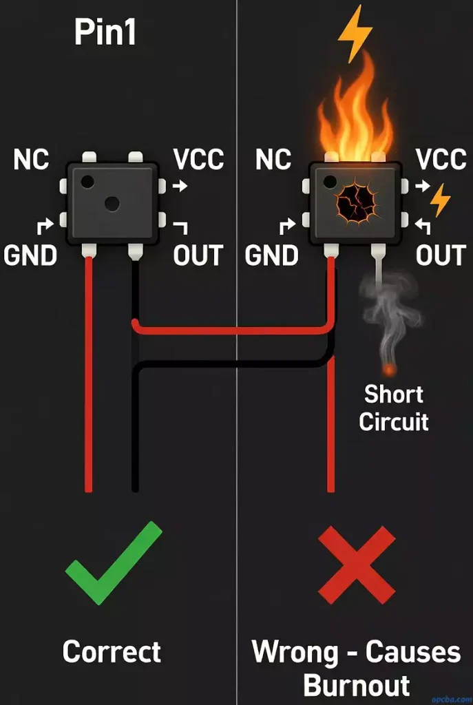
1. Reverse Power Polarity
A typical active crystal oscillator has four pins with a standard definition: Pin 1 is floating (or tri-state), Pin 2 is ground (GND), Pin 3 is output (OUT), and Pin 4 connects to the voltage supply (VCC). If you accidentally connect the power supply to the ground pin during PCBA processing, a strong reverse current instantly breaks down the internal IC. This renders the crystal oscillator useless immediately.
2. Incorrect Input Voltage Specification
Active crystal oscillators have strict rated voltage requirements. Common ratings include 1.8V, 2.8V, 3.3V, and 5V.
Risk: If you supply 5V to a crystal oscillator rated for 1.8V, the excessive electric field stress immediately damages the internal circuit’s PN junction. This leads to chip overheating and breakdown—what we refer to as “burnout.”
Key Action Points to Prevent Crystal Oscillator Burnout
- Control soldering strictly: Keep soldering temperature and time within limits. Use reflow soldering first, and confirm the temperature profile meets specifications.
- Check circuit design: Verify that the passive crystal oscillator’s drive power stays within the datasheet’s allowed range.
- Confirm power details: For active crystal oscillators, double-check the power pin definition and voltage rating. This prevents reverse connections or overvoltage. Discover how diodes can help prevent reverse voltage and overvoltage issues in your PCBA design in our post What is the use of diodes in PCBA processing?
- Add ESD protection: Use Electrostatic Discharge (ESD) protection to avoid electrostatic damage during handling and shipping.
By following these technical troubleshooting steps and best practices, we aim to help your PCBA projects avoid the headaches of crystal oscillator burnout.


