At some point, every power electronics designer hits the thermal wall of organic laminates. You can add copper pours and thermal vias, but the heat still pools under the IGBT module. That’s usually when the conversation shifts to an alumina ceramic PCB. It’s a different animal from FR-4—copper is bonded straight to the ceramic surface under high temperature, forming a board that conducts heat almost like a metal part while keeping its electrical isolation intact. The result is a substrate that can carry heavy currents, handle voltage stress, and survive temperatures that would delaminate standard boards in minutes.
Why Ceramic Shows Up in High-Power Designs
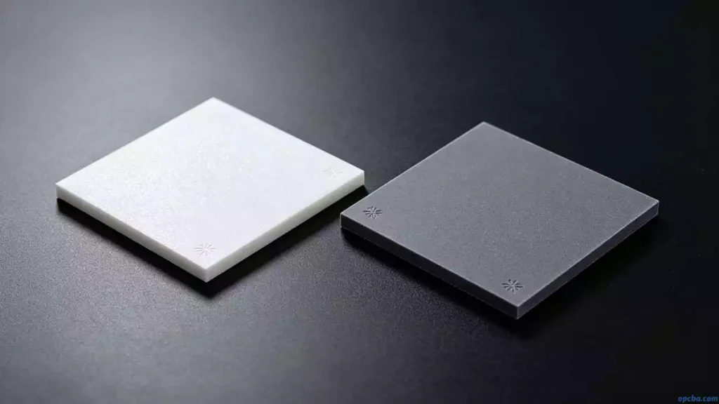
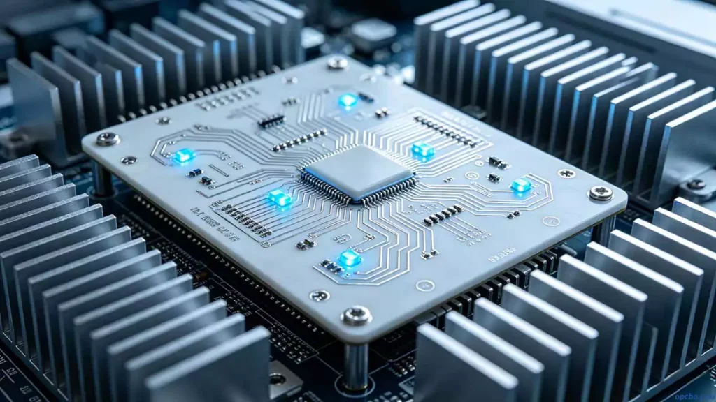
An alumina ceramic PCB uses Al₂O₃ as the base—a material with superb electrical insulation, high thermal conductivity, and strong adhesion to copper. Once the copper foil is bonded (single or double side), it can be etched into circuit patterns just like a standard PCB. The difference comes in current capacity: the ceramic underlayer pulls heat out fast, letting traces run denser and hotter without failure. This makes it a go-to for power modules, high-frequency supplies, RF amplifiers, and motor drives. I’ve specified ceramic PCB substrate materials when a standard IMS board simply couldn’t dump the watts fast enough. For details on our aluminum PCB offerings, see our product page: Aluminum PCB
The Bigger Ceramic Family: Al₂O₃, AlN, and BeO
While alumina dominates the ceramic PCB substrate market, it’s not alone. Beryllium oxide (BeO) offers even higher thermal conductivity but brings toxicity concerns during machining. Aluminum nitride has emerged as a compelling middle ground. An AlN ceramic PCB delivers thermal conductivity that can reach 170–200 W/m·K, paired with a low CTE that closely matches silicon die. That reduces die-attach stress during thermal cycling. The trade-off? Processing is more demanding and the raw material cost runs higher than Al₂O₃.
When a design has tight thermal margins and cannot tolerate the CTE mismatch of a polymer or metal-core board, I lean toward an AlN ceramic PCB even knowing the price premium. For less extreme cases, Al₂O₃ at 20–30 W/m·K gets the job done.
Making the Board: From Powder to Sintered Layer Stack
The manufacturing path for these boards depends on the architecture. Direct Bonded Copper bonds copper foil to the ceramic under heat and pressure, producing a thick copper layer that suits high current paths. High-temperature co-fired ceramic takes a different route. The ceramic powder—often Al₂O₃ or AlN—mixes with organic binders to form a slurry, which is cast into thin green sheets. Each sheet is mechanically drilled for vias, screen-printed with conductive paste (tungsten or molybdenum for HTCC), and then stacked and pressed together with the other layers. Sintering happens around 1600°C in a controlled atmosphere furnace.
This process limits conductor choices to refractory metals with higher resistance than copper, so trace losses must be modeled carefully. Thermal conductivity for HTCC sits between 20 and 200 W/m·K, driven by the ceramic purity and powder composition. Low-temperature co-fired ceramic, by contrast, fires below 900°C and allows silver or copper conductors, but with different trade-offs in mechanical strength and thermal performance. The choice between HTCC, LTCC, DBC, and thick-film deposition usually comes down to layer count, current requirements, and whether you need buried passives.
How Ceramic Stacks Up Against Polymer and Metal Substrates
Electronic packaging draws from four substrate families: polymer, metal, composite, and ceramic. The high thermal conductivity PCB made from ceramic beats polymer and composite boards on nearly every thermal and mechanical metric. Dielectric constant stays low and stable at high frequency, an asset in RF and microwave work. Insulation resistance and hermeticity hold up in humid conditions where organic boards swell. The coefficient of thermal expansion sits close to silicon, reducing solder fatigue.
The list of positives runs long. The headline negative is cost. An alumina ceramic PCB costs significantly more than an equivalent FR-4 or MCPCB, and not every fab has the in-house capability. Brittleness also demands careful handling during assembly and mounting. For designs that require repeated mechanical fastening or flex, ceramic is rarely the right answer.
Where It All Lands
Choosing a high thermal conductivity PCB means weighing thermal headroom against budget and supply chain access. Alumina ceramic remains the volume workhorse for power and RF. Aluminum nitride covers the highest-performance socket. The manufacturing process selected—DBC, HTCC, LTCC—dictates trace conductivity, via fill options, and final cost. Get those variables sorted early with your fabricator, and a ceramic board becomes a predictable, reliable thermal engine rather than a last-resort gamble.


