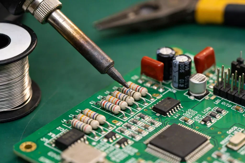
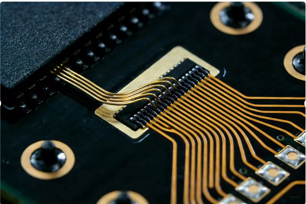
Many engineers still encounter unexpected problems even after completing PCB assembly. In most cases, these issues can be avoided through a systematic debugging process. In this guide, we will walk through 5 practical PCB debugging steps that help identify short circuits, improve troubleshooting efficiency, and reduce the risk of power-on failure.
Quick PCB Short Circuit Testing Checklist
Before powering on a PCB, make sure the following items have been checked:
- PCB Debugging Checklist Status
- Check PCB wiring and schematic connections ✔
- Verify component polarity ✔
- Test for short circuits on power rails ✔
- Inspect solder joints and bridges ✔
- Perform continuity testing with a multimeter ✔
- Confirm input impedance is normal ✔
Completing these checks can significantly reduce PCB troubleshooting time and help prevent board damage.
Pre-Power-On Inspection
After assembling a PCB, never apply power immediately. Before powering on the board, perform the following inspections carefully to ensure every stage is correct.
1.1 Check Whether the Connections Are Correct
Start by reviewing the schematic diagram carefully. Pay special attention to:
Power supply labels and network node definitions
Overlapping network nodes
Component footprints and package models
Pin sequence consistency
For non-through-hole packages, avoid checking pin orientation based only on top-view assumptions.There are two common methods for PCB wiring inspection:
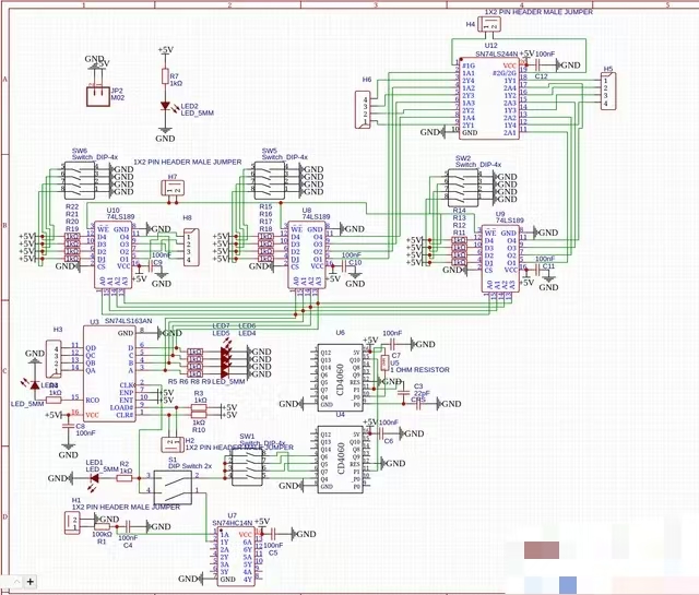
Method 1: Check According to the Schematic
Verify each installed connection step by step according to the circuit diagram.
Method 2: Check According to the Actual PCB Layout
Inspect each component individually and trace its pin connections to confirm that every connection matches the schematic.
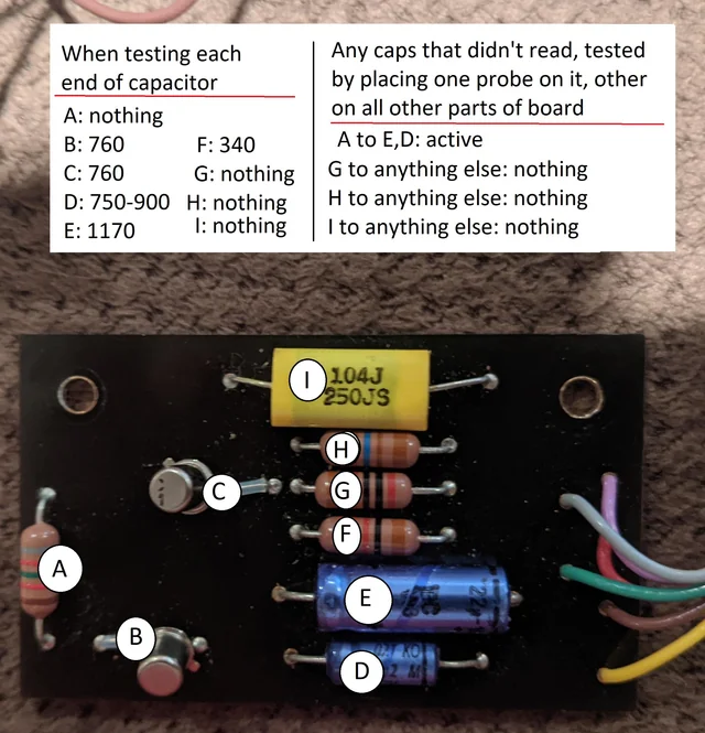
To avoid mistakes, mark every verified connection on the schematic. A multimeter in continuity mode is strongly recommended because it can also help detect poor solder joints or broken traces.This step is extremely important when learning how to find a short circuit on a PCB board.
1.2 Inspect Component Installation
Check the following carefully:
Short circuits between adjacent pins
Poor solder joints or loose connections
Incorrect polarity of diodes, transistors, ICs, and electrolytic capacitors
Possible power input short circuits
A multimeter in diode or continuity mode can help detect solder bridges and shorted areas while moving the probes across the PCB surface.Before applying power, always measure the input impedance of the power rail. This is one of the most effective ways to detect a PCB short circuit before damaging components.
1.3 Use 0-Ohm Resistors for Safer Debugging
A common PCB debugging method is to place a 0-ohm resistor in the power supply section during circuit design.
Do not solder this resistor before initial testing. First verify that the power supply voltage is stable and correct. After confirming the voltage, solder the resistor to supply power to the remaining circuits.
This method helps prevent IC damage caused by abnormal power conditions and makes electronic board troubleshooting much safer.It is also recommended to include protection circuits such as resettable fuses in the PCB design.
1.4 Perform Open-Circuit and Short-Circuit Testing
Before powering on the PCB, always perform:
Open-circuit testing
Short-circuit testing
Continuity testing
Properly designed test points can greatly improve debugging efficiency. In high-speed PCB circuits, 0-ohm resistors can also simplify isolation testing and fault diagnosis.Only after completing all pre-power-on inspections should the PCB be powered on.
Power-On Testing
2.1 Initial Power-On Observation
After applying power, do not immediately measure electrical parameters. First, observe whether there are any abnormal conditions, such as:
Smoke
Burning smell
Overheating IC packages
Abnormal heating on power components
If any abnormality occurs, immediately shut down the power supply and troubleshoot the issue before testing again. This is one of the most critical steps in PCB short circuit troubleshooting.
2.2 Static Debugging
Static debugging refers to DC testing without input signals or only with fixed-level signals.
Using a multimeter, measure the voltage at different points in the circuit and compare the results with theoretical values. Combined with circuit analysis, this helps determine whether components are damaged or operating outside their normal range. Replace or adjust components as necessary until the circuit reaches the expected operating condition.
2.3 Dynamic Debugging
Dynamic debugging is performed after static debugging is completed successfully.
Apply appropriate input signals to the circuit and monitor output signals step by step along the signal path. If abnormal signals are detected, analyze the cause and eliminate the fault before continuing. During testing, never rely on assumptions alone. Always use professional measurement instruments. When using an oscilloscope, it is recommended to set the input coupling mode to DC so both AC and DC components can be observed simultaneously.
After debugging, verify whether the system meets the required specifications, including:
Signal amplitude
Waveform shape
Phase relationship
Gain
Input impedance
Output impedance
If necessary, optimize circuit parameters further.
Additional PCB Debugging Tips
Prepare a PCB Debugging Plan
Before testing, define:
Debugging procedures
Measurement methods
Test points
Mark all test points clearly on both the schematic and the PCB. Preparing a debugging data sheet in advance can also improve testing efficiency.
Keep the Workbench Organized
Set up a clean and organized debugging workstation with all required instruments easily accessible. Many engineers overlook this issue. A cluttered workspace containing tools, books, clothing, and instruments mixed together can seriously affect PCB troubleshooting efficiency.
Select Proper Measurement Instruments. Choose measuring instruments according to the circuit requirements. The instrument accuracy should always exceed the accuracy requirements of the system being tested.
Common tools for electronic board short circuit testing include:
- Digital multimeter
- Oscilloscope
- Power supply
- Logic analyzer
- Thermal camera
- Follow the Signal Flow During Debugging
PCB debugging should generally follow the signal flow direction. The output signal from one stage can serve as the input signal for the next stage, creating better conditions for full-system debugging.
Debugging Digital Circuits
For digital circuits using programmable logic devices, complete the following steps:
- Source file input
- Logic debugging
- Program downloading
Then integrate the programmable logic device with the analog circuit and perform full system testing.
Record All Test Results Carefully
During debugging, carefully observe and analyze all test phenomena and maintain detailed records to ensure the completeness and reliability of experimental data.
Common Causes of PCB Short Circuits
The most common causes of PCB short circuits include:
- Solder bridges
- Incorrect component polarity
- Damaged ICs
- PCB manufacturing defects
- Metal debris on the board
- Excessive solder paste
- Incorrect wiring or layout mistakes
Understanding these common issues can help engineers troubleshoot PCB failures more efficiently.
In the next article, we will continue with two advanced PCB short-circuit testing techniques, including thermal analysis and segmented power injection methods, to help engineers locate hidden faults more efficiently.
Stay tuned for Part 2 of this PCB debugging guide.