Getting a connector or wire to stay put on a flexible circuit is not the same game as soldering on rigid FR4. The board moves. The heat path is different. And rework often turns a good flex into a wavy, delaminated mess. If you’re new to working with these boards, start with our foundational guide: Basic information of flexible printed ciruicts boards
I’ve learned that flex PCBA soldering hinges as much on fixturing and thermal profiling as it does on the soldering technique itself. Here’s a breakdown of the three common paths, ordered from least to most reliable in volume.
Manual Soldering: Cheap, but the First Source of Field Returns
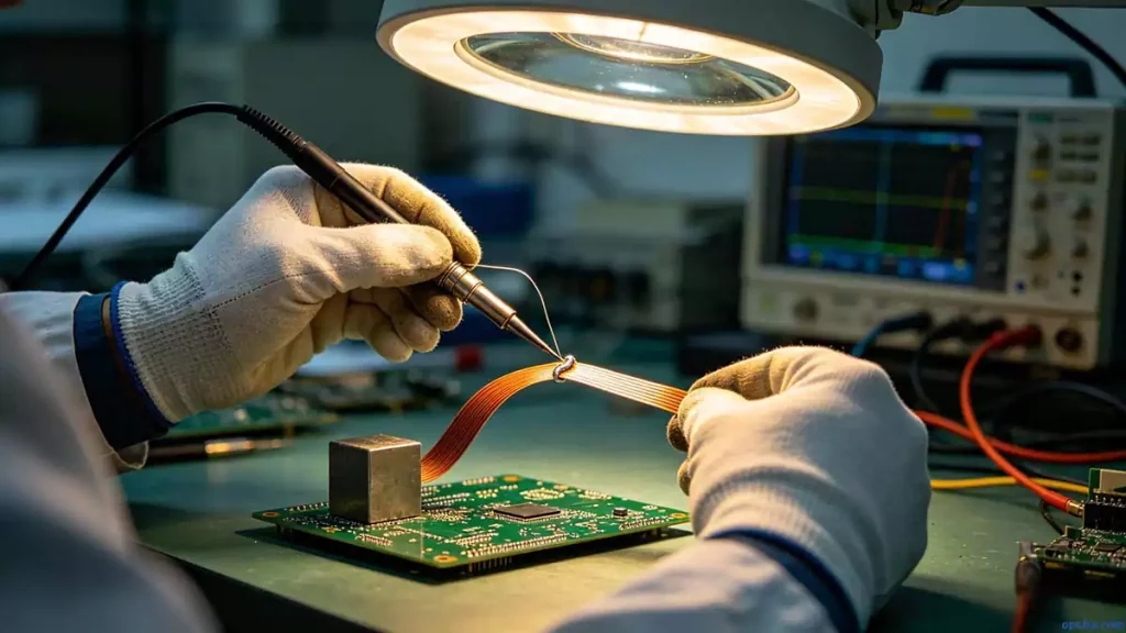
Manual soldering flex boards with a temperature-controlled iron is the lowest-cost entry point. No custom carriers, no programming—just a steady hand. For a quick bring-up with unlocked designs, it’s fine. I often see R&D teams use hand-soldered flex prototypes for functional checks before the fix and revise the layout.
The problem is consistency. The flex board’s natural tendency to lift or warp as the iron pulls away means the joint can shift before it solidifies. That’s where cold joints and solder bridges originate. To counter this, I keep a small weight on the flex near the joint until the fillet sets. For gold-finger pads, drilling a through-hole helps confirm that the solder wetted fully, and it acts as a relief that reduces bridging from excess solder. But even with these tricks, manual soldering flex is not a mass-production process. I’d never ship a volume build where every joint depended on an operator’s touch.
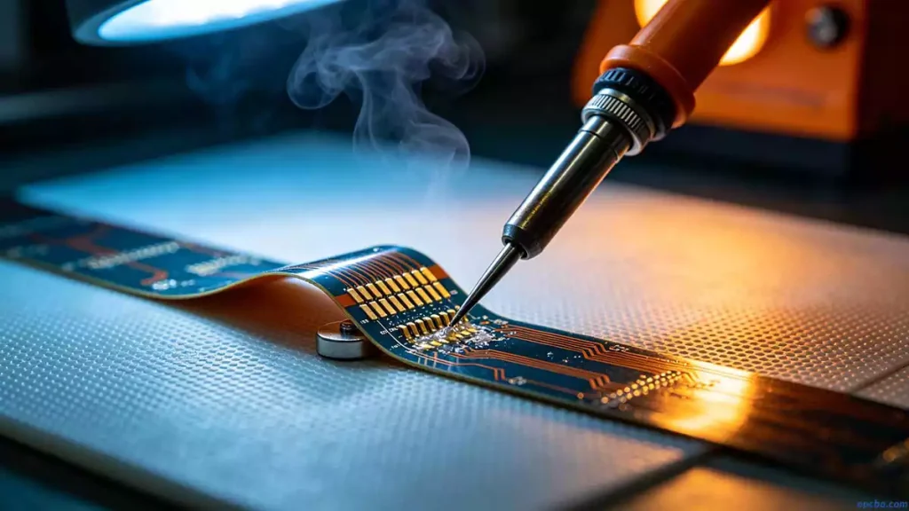
HotBar Soldering: When Pulse Heat Meets a Fixture
HotBar soldering solves the warping problem by clamping the FPC and PCB together before heating. A pulse current pushes through a high-resistance thermode, which heats up and reflows the solder paste printed on the pads. The process needs a dedicated machine, a carrier to hold both boards, and stable process parameters. Once dialed in, it achieves repeatable results—which is why flex PCBA soldering in volume almost always leans on HotBar or similar thermode bonding.
Design decisions around the gold-finger pitch make or break yield. A 0.5 mm pitch is far more forgiving than 0.3 mm, and trace routing near the bond area must avoid sharp corners that concentrate stress and crack after flexing. Process control is equally hands-on: solder paste volume has a tiny window, flux application must cover the entire joint area, and the temperature-pressure-time profile needs to be calibrated to the board thickness and pad geometry. Some thin flex boards struggle with heat transfer through the stack-up. In those cases I’ve moved to SnBi low-temperature solder paste to avoid scorching the polyimide, but then had to add mechanical reinforcement because the joint is more brittle.
HotBar soldering isn’t “set and forget.” The thermode pressure must ramp smoothly, otherwise the carrier shifts and the interconnect thickness varies. I always run cross-sections on the first batch to measure the intermetallic layer thickness and look for voids.
Reflow and Wave Soldering on Flex Boards
When flex board reflow becomes necessary—for example, placing QFNs or BGAs on a rigid-flex assembly—the prep work starts long before the oven. Bake the bare flex panels first. Polyimide absorbs moisture, and a rapid ramp to reflow can cause delamination or blistering. A typical bake at 125°C for 4–6 hours drives out that moisture.
The reflow profile itself needs a gentler preheat slope than a rigid board of the same thickness. I cap the peak temperature at 245°C and limit time above liquidus to the shorter end of the paste manufacturer’s recommendation. Higher peaks increase the risk of board popcorning and discoloration. For hand-soldered touch-ups on reflowed flex assemblies, I keep the iron at 350°C and count to three—no longer. Localized heat on a thin flex can blister the coverlay in seconds.
When the Board Pops: Avoiding Delamination
A blown board on the production line is a costly wake-up, especially on high-CTI materials. Prevention starts with moisture management but also includes thermal stress control through the entire assembly flow. I’ve found that tracking each panel’s exposure time between bake and reflow, and not letting it queue overnight in an unconditioned area, dramatically cuts the defect rate. Controlling the reflow ramp rate and peak temperature removes the primary triggers. Once those are dialed in, board popping becomes a rare event rather than a weekly production hold.
In the end, successful flex PCBA soldering is about matching the method to the build volume and the board’s physical limits. Hand solder for exploration, HotBar for high-volume flex-to-board interconnects, and flex board reflow for complex assemblies—but only after a bake and a well-tuned profile. Keep a weight handy, double-check your cross-sections, and don’t let the board get away from you before the joint sets.


