Automotive millimeter-wave radar has moved from an option on high-end models to standard equipment across the industry, and demand for the automotive millimeter-wave radar PCB behind it has followed.
The interesting question is no longer whether radar goes into a vehicle, but what the sensor generation now shipping asks of the board underneath it.
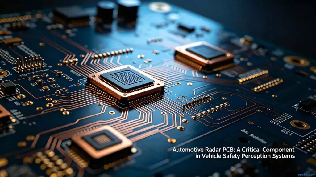
What 4D radar changes for the board
Modern vehicles are shifting toward 4D millimeter-wave radar, which adds a vertical dimension to what a standard sensor can see. Instead of a flat picture of distance and bearing, a 4D radar returns coordinate data in three dimensions, which makes fusion with cameras and lidar both simpler and more accurate.
The vertical dimension comes from extra antennas and extra processing. That combination lets the sensor separate moving targets from stationary ones and tell them apart by height, which is what makes overhead signs, bridge decks and kerbs distinguishable from vehicles in the same lane.
Adding that dimension changes what the board has to do. More antennas mean more RF channels in the same footprint, and the shift to 77 GHz and 79 GHz radar means those channels run at shorter wavelengths, where every layout detail counts for more.
Key supported functions include:
- Surround millimeter-wave radar perception
- Environment modeling and freespace detection
- Automated parking (APS)
- Target classification
- SLAM localization based on environmental landmarks
What the extra channels ask of the board
Channel count is the first pressure point. A 4D sensor needs a two-dimensional antenna array, and every element in that array is another RF path that has to be matched and kept isolated from its neighbours. On a fixed board outline, that pushes layer count up and forces tighter trace and spacing rules.
The second is consistency between channels. A phased array only works when the phase relationship between elements is predictable, so the electrical length from each antenna to the transceiver has to match within tight limits. That turns material uniformity into a design parameter: a laminate whose dielectric constant drifts across the panel will put channels out of step even when the artwork is correct.
Then there is coexistence. A 4D radar produces far more data than a 3D sensor, so high-speed digital interfaces share the board with sensitive RF front ends. Partitioning the stackup, keeping a continuous reference plane under the RF section and shielding the digital side are what keep the two from interfering.
Power and heat follow the same curve. More channels switching at higher rates raise dissipation, and the thermal path out of the board becomes part of the electrical design.
Where the manufacturing difficulty sits
Design intent only survives if fabrication can hold it. On a 4D array the tolerances that matter are dielectric constant consistency across the panel, copper thickness control and etch tolerance on fine traces, because each of those shifts electrical length.
Mixed stackups add a second layer of difficulty. Radar boards commonly combine a low-loss laminate for the antenna and RF layers with FR-4 for the digital and power sections, and the two materials behave differently under lamination. Press parameters that suit one will distort the other, so the schedule has to be built around the pair.
Assembly is the last place to lose performance. Port-to-port phase accuracy depends on placement accuracy, solder volume and the absence of voids under the RF ground pads, which is why high-frequency radar PCB production is judged on process control more than on the equipment list.
Where the demand is heading
The spread of millimeter-wave radar through intelligent vehicles has lifted the market for automotive millimeter-wave radar PCB year on year, and the move to 4D is adding a second wave of demand on top of the 3D volume.
As perception systems take on more of the driving task, the boards behind them are asked for tighter impedance control, lower loss and better thermal behaviour at the same time.
Boards for 4D radar are built to order, so the conversation starts with the stackup and the tolerances it has to hold.
Contact our team with a stack and we can tell you where the risk sits.