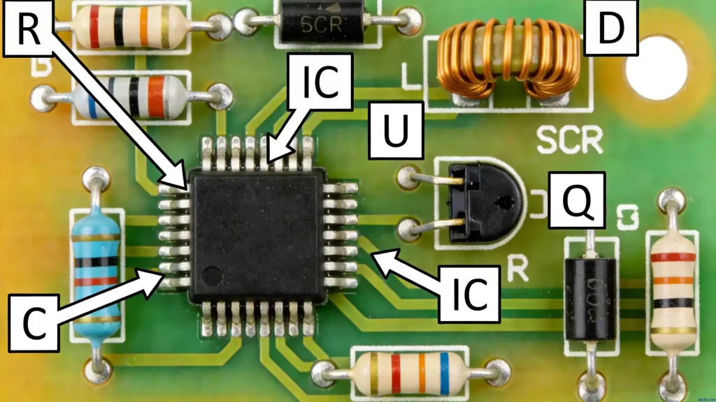
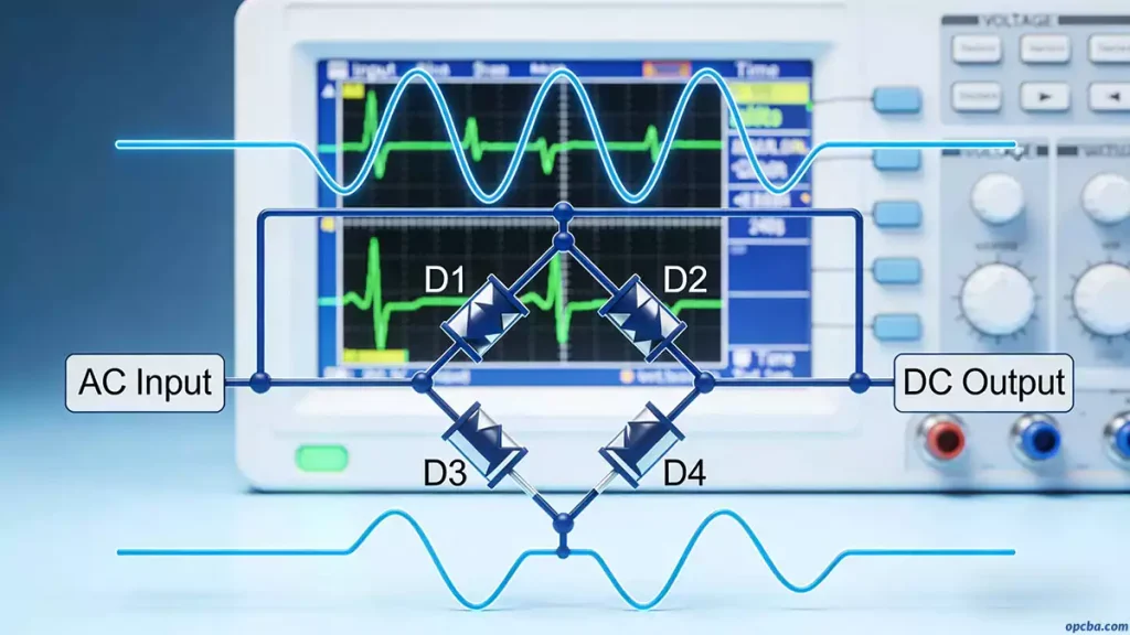
In PCB testing, the fixture’s internal wiring system—pcb-based fixture wiring—directly determines test reliability, fixture lifespan, and long-term maintenance costs. Yet most discussions in the industry stop at “which probe to use” or “what material to specify,” without treating pcb-based fixture wiring as a standalone engineering discipline. This guide aims to fill that gap. If you’re new to core printed circuit board fundamentals and basic terminology, start with our foundational overview: Printed Circuit Board(PCB)
At OPCBA, we’ve seen this firsthand across thousands of PCB assembly and testing projects. The difference between a well-designed fixture wiring system and a poorly executed one isn’t just technical—it’s financial. Rework, false failures, and debugging hours add up quickly.
What Is PCB-Based Fixture Wiring?
PCB-based fixture wiring refers to the practice of routing signals through a dedicated printed circuit board inside a PCB test fixture, rather than using hand-wired point-to-point connections.
Traditional fixtures rely on manual wiring—operators use wire wrapping guns to connect probe sockets to the test system interface, one by one. With fewer than 50 test points, this works. Beyond that, you’re looking at what industry veterans call a “rat’s nest”: tangled wires, illegible labels, and a fixture that no one wants to open for maintenance.
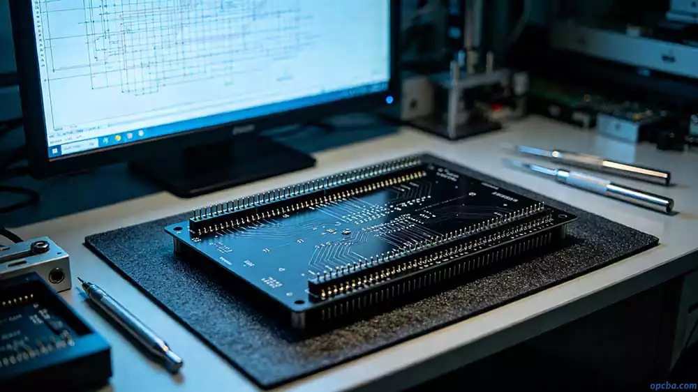
PCB-based fixture wiring takes a fundamentally different approach: probe sockets solder directly onto a custom PCB, which connects to the test system through standard connectors. No flying leads. No guessing games. Just engineered, repeatable signal paths.
The shift is from craft-based assembly to engineered design—and that’s precisely where OPCBA’s PCB fabrication and assembly capabilities come into play.
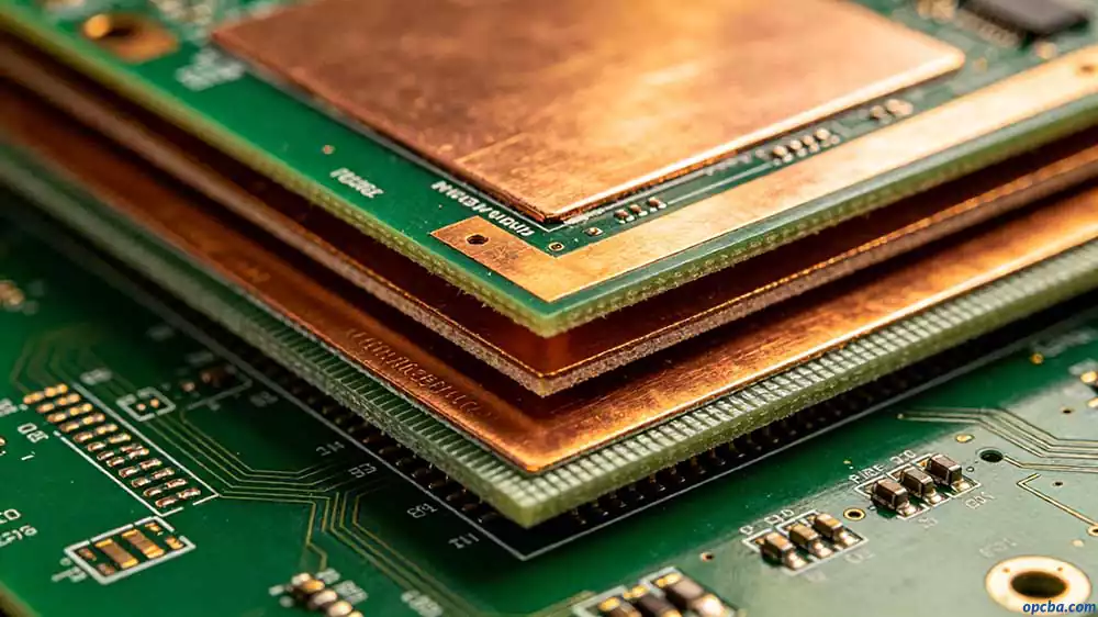
Why UL94V-0 and 4-Layer PCB Matter for Fixture Wiring
When sourcing a pcb-based fixture wiring solution, UL94V-0 and 4-layer PCB are two specifications that frequently appear. Are they marketing buzzwords, or legitimate requirements?
UL94V-0 is a flammability standard for plastic materials. Standard FR-4 already meets UL94V-0 requirements—the “FR” stands for Flame Retardant. In fixture applications, UL94V-0 matters because fixtures carry power traces. In a short-circuit or overload scenario, flame-retardant material prevents fire from spreading. This isn’t a “nice-to-have”—it’s a basic safety baseline. If your fixture needs to pass safety certifications (UL, CE, etc.), UL94V-0 is effectively mandatory.
4-layer PCB delivers value through signal integrity. A 2-layer board can route signals, but fixture wiring often carries a mix of power, ground, high-speed control signals (JTAG, SPI), and analog signals. A 4-layer board provides dedicated power and ground planes in the inner layers, dramatically reducing loop inductance and signal crosstalk. In practice, 4-layer construction also enables higher wiring density—when you’re dealing with more than 100 test points, 2-layer boards quickly run out of routing space.
When can you step down? Under 50 test points, low signal rates (<1MHz), and continuity-only testing—a 2-layer board without UL94V-0 material might suffice. But for high-volume production fixtures that need to run reliably for years, UL94V-0 with 4-layer PCB isn’t optional. It’s the default.
OPCBA’s PCB manufacturing capabilities support exactly this specification range, from prototype to high-volume production, with full material traceability and quality control.
Four Implementation Approaches for PCB-Based Fixture Wiring
1. Bed-of-Nails Fixture Wiring
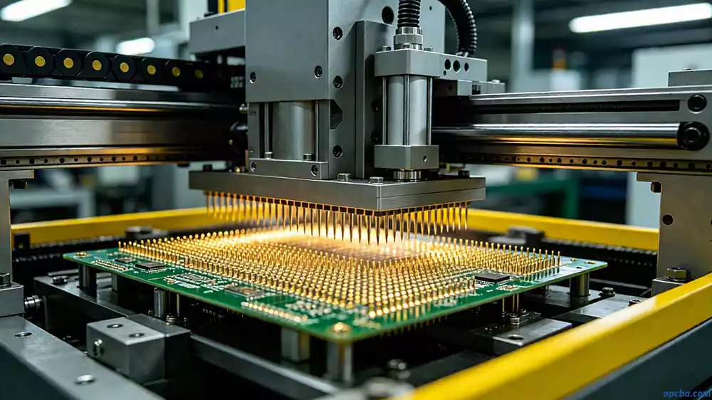
The classic fixture form. Arrays of spring-loaded pogo pins contact PCB test points in a single press, completing all tests simultaneously. In bed-of-nails fixtures, pcb-based fixture wiring typically involves soldering probe sockets onto an interface PCB, which connects to the test system via ribbon cables or board-to-board connectors.
Best for: High-volume production, 50–500+ test points, high-speed testing.
Watch out: Bed-of-nails fixtures demand high precision in PCB test point design. Any PCB design change means fixture rework—and that cost adds up.
2. Functional Test Fixture Wiring
Functional test fixtures power up the PCB, apply loads, and inject signals to verify actual operation. The pcb-based fixture wiring in these fixtures tends to be more complex—routing not just test signals, but also power distribution, load connections, and signal generator interfaces.
Best for: Final product validation, “live” functional testing.
3. Flying Probe Testing (Fixtureless)
Flying probe testers use moving probes to contact test points sequentially—no traditional fixture required. Strictly speaking, this falls outside pcb-based fixture wiring, but it’s an important alternative for low-volume, high-mix scenarios.
Best for: Low-volume production, prototype validation, low test-point counts.
4. Auto TPCB (Automated Test PCB Wiring)
This is an advanced form of pcb-based fixture wiring—signal routing is fully realized through PCB and the design process is automated. Compared to manual wiring, Auto TPCB offers: zero wiring errors, turnaround times comparable to simple fixtures, and no additional NRE fees.
Best for: Test points >50, multiple fixture copies needed, limited in-house EE resources for manual wiring design.
PCB-Based Fixture Wiring: Step-by-Step Design Process
Step 1: Test Point Planning and DFT Review
Before any routing begins, verify the PCB’s test point design:
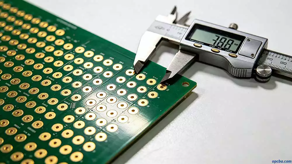
- Test point pad diameter: 0.8–1.2mm recommended. Below 0.6mm, probes tend to miss; above 1.5mm, you’re wasting space.
- Test point pitch: Minimum 1.27mm (50mil) center-to-center—otherwise probe sleeves will interfere.
- Test point distribution: Spread evenly across the PCB. Clustering creates uneven force on the fixture.
- Single-side principle: Put all test points on one side of the PCB (typically the bottom) whenever possible. Single-side fixtures cost roughly 40–50% of double-side designs.
- Ground test points: At least 2 GND test points. Each power rail (3.3V, 5V, 12V, etc.) needs at least one test point.
Step 2: Probe Selection and Layout
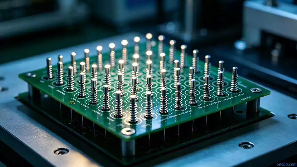
Probe selection directly impacts pcb-based fixture wiring reliability:
- Probe tip type: Match tip geometry to test point surface (sharp, crown, serrated, etc.).
- Spring force: Standard range is 100–150g. Adjust for specific applications.
- Layout density: Aim for 3–5 test points per square centimeter. Higher density creates uneven force distribution on the fixture plate.
- Tooling pins: At least two locating pins diagonally across the PCB ensure repeatable positioning.
Step 3: Signal Routing
This is the core of pcb-based fixture wiring design:
- Signal grouping: Separate analog, digital, power, and ground signals. Avoid long parallel runs between different groups.
- Ground handling: Place a ground trace adjacent to each critical signal (e.g., JTAG TAP signals). Use twisted pairs or parallel-pair routing.
- Trace length: Keep it short—especially for high-speed signals.
- Wire gauge: Signal lines typically use 30–28AWG. Power lines require heavier gauge based on current draw.
In practice, this step consumes the most time. Beyond 100 test points, manual routing effort escalates exponentially—which is exactly where Auto TPCB and OPCBA’s engineering support become valuable.
Step 4: Interface Definition and Standardization
The interface between fixture and test system needs clear definition:
- Connector selection: Choose based on signal count—pin headers, D-Sub, or custom interfaces.
- Pin mapping: Create a clear pin mapping table. Every probe → PCB trace → connector pin path must be traceable.
- Labeling and documentation: Every interface, every signal line needs clear identification. This isn’t “extra”—it’s what saves you during maintenance.
Common Failure Modes and Troubleshooting
When pcb-based fixture wiring fails, here’s how to diagnose the three most common issues:
1. Intermittent Contact
Symptom: Unstable test results—same PCB passes sometimes, fails others.
Troubleshooting: Start with a multimeter to check probe-to-interface continuity (static). Then run repeatability tests with a known-good PCB (dynamic). If problems cluster around specific test points, suspect probe spring fatigue or tip oxidation on those points.
2. Signal Crosstalk
Symptom: Low-frequency tests pass; high-frequency or high-speed signal tests fail intermittently.
Troubleshooting: Check whether sensitive signals in your pcb-based fixture wiring run parallel to noise sources (power traces, clock lines) for extended distances. A 4-layer PCB with solid ground planes mitigates this significantly—which is why 2-layer boards carry much higher crosstalk risk.
3. Wiring Errors Causing Diagnostic Ambiguity
This is the most insidious failure. When a test fails, you can’t tell whether it’s the PCB itself, the test code, or a miswired fixture connection.
Troubleshooting: Use a known-good “Golden Board” as a benchmark. If the Golden Board fails, the problem is in the fixture or test system—start with a continuity test to rule out wiring errors, then move to test code. For more systematic PCB debugging methodologies and common pitfalls to avoid in daily engineering work, refer to our comprehensive guide:PCB Troubleshooting Guide: Common Debugging Mistakes and Fault Diagnosis Methods
Selection Decision Framework
| Test Points | Fixture Copies | EE Resources | Recommended Approach |
|---|---|---|---|
| <50 | 1–2 | Available or not | Hand wiring (lowest cost) |
| 50–150 | 1–2 | Available | PCB-based (manual design) |
| 50–150 | ≥3 | Not available | Auto TPCB (automated design) |
| >150 | Any | Any | Auto TPCB (only viable path) |
The core logic: Beyond 50 test points, manual wiring error rates and maintenance costs rise quickly. If your project requires multiple fixture copies, the marginal cost per fixture with a PCB-based approach is far lower than hand wiring—because PCB design is a one-time investment, and subsequent copies only require PCB fabrication and assembly.
Whichever approach you pick, the fixture body has to be built to match. Our PCB test fixture guide covers how the frames, probe modules, and fabrication specifications are defined, and what your factory needs from you to quote one.
This is precisely where OPCBA’s one-stop model delivers value: PCB design, fabrication, assembly, and testing—all under one roof, with full quality control at every stage.
Final Thoughts
PCB-based fixture wiring isn’t a new concept, but the industry’s discussion of it remains surprisingly shallow. Most content stops at “what is a fixture” and “what are the types,” leaving the real questions—how to design, how to select, how to troubleshoot—largely unanswered.
This guide attempts to fill that gap. From the practical meaning of UL94V-0 and 4-layer PCBs, to a comparison of four implementation paths, to specific routing steps and failure diagnosis—it’s designed as an actionable reference for engineers designing or sourcing test fixtures.
One final piece of advice: If your test points exceed 100, if you need multiple fixture copies, or if you simply don’t want to get called back to the factory at midnight to debug a wire that “went somewhere”—take pcb-based fixture wiring seriously. The upfront cost may be slightly higher, but the time and headaches you save over the long run far outweigh the difference.