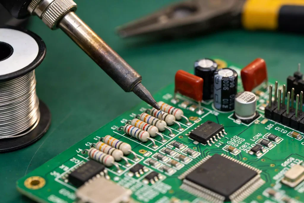
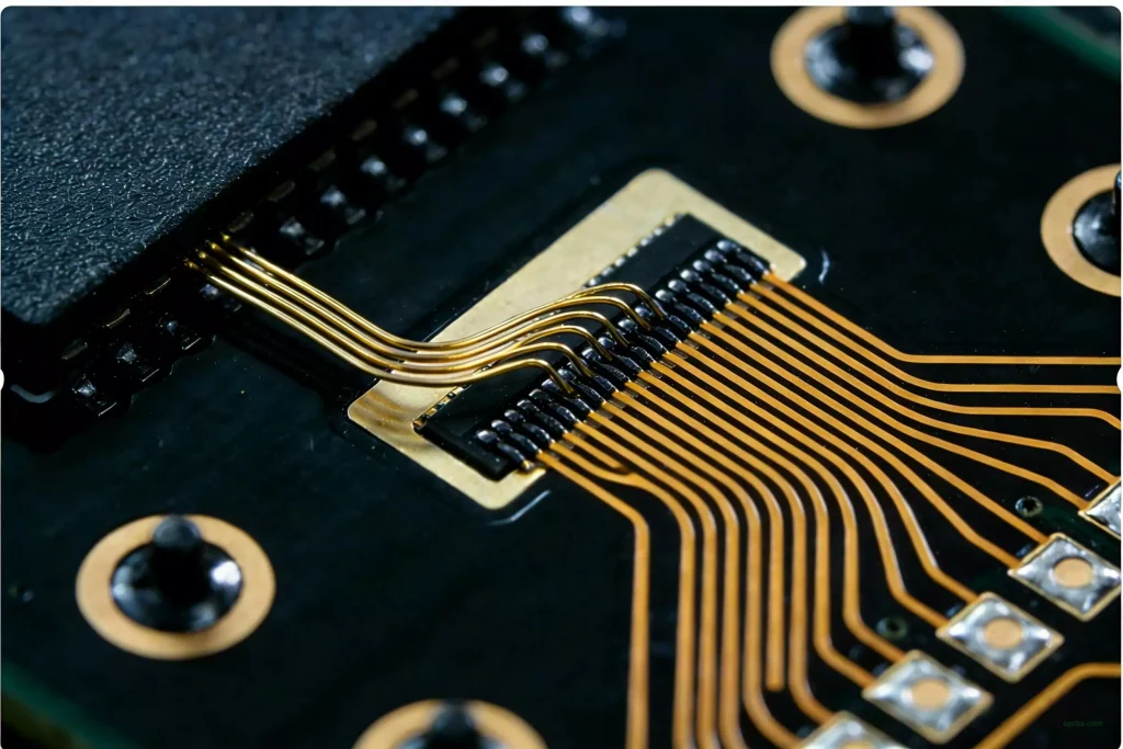
When a component dumps several watts through a tiny pad, the board stops being just a conductor. It becomes the heatsink. That is where an aluminum substrate PCB earns its place.
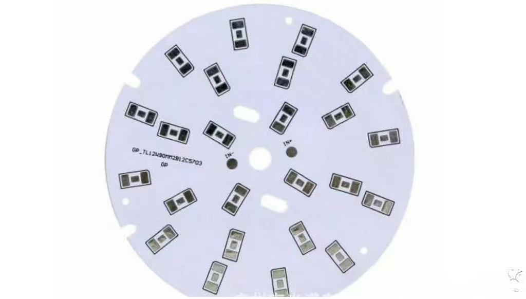
The Heat Path in an Aluminum Substrate
Heat flows: component → solder → copper circuit layer → dielectric → aluminum base → ambient.
The dielectric is the bottleneck. Its thermal conductivity, 1 to 3 W/m·K, and its thickness set the thermal resistance, typically 0.5 to 3.0 °C/W for the whole stack. A thinner, higher-conductivity dielectric drops that number and lets the aluminum base do what it does best: spread heat fast. Base conductivity is around 200 W/m·K. Those two figures together decide how much heat actually reaches the metal, which is where the advantages of an aluminum core board in heat dissipation start.
Aluminum vs FR-4: The Numbers
| Property | FR-4 | Aluminum substrate |
|---|---|---|
| Thermal conductivity | ~0.3 W/m·K | dielectric 1 to 3, base ~200 |
| Relative heat spread | 1x | ~8 to 10 times |
| Typical thermal resistance | high | 0.5 to 3.0 °C/W |
| Cost | low | moderate (still less than ceramic) |
When You Must Switch to Aluminum
Consider a metal core board when:
- Junction temperature would exceed the device rating on FR-4.
- A heatsink plus FR-4 solution is too bulky or too heavy.
- LED arrays show color shift or early failure from hot spots.
- High-current traces need to run cooler to avoid delamination.
Selecting the Right Aluminum Substrate
- Dielectric conductivity: pick 2 to 3 W/m·K for aggressive cooling; 1 W/m·K is enough for many LED jobs.
- Copper weight: 2 oz (70 µm) and up for power; match to your current load.
- Base thickness: 1.0 to 3.0 mm; thicker spreads heat better but adds weight.
- Surface finish: HASL, ENIG, or OSP depending on assembly and shelf life.
New to aluminum PCBs? Start with the structure and applications overview.
Get a metal core PCB built to your thermal spec.
Need a thermal simulation or stack-up review? Talk to OPCBA’s engineering team before you freeze the layout.