If you’re designing antenna arrays for 5G base stations, 77GHz automotive radar modules, or any RF circuit operating at microwave frequencies, you’ll quickly run into a question: can FR4 handle it?
In many cases, the answer is no—not because FR4 is “bad,” but because its dielectric loss and material variation become significant factors at higher frequencies. The dielectric material introduces additional loss through polarization effects, causing RF energy to dissipate as heat. By the time your signal reaches the other end of the board, it may have attenuated to an unusable level. If you’re new to core printed circuit board fundamentals and basic terminology, start with our foundational overview: Printed Circuit Board(PCB)
That’s where Teflon PCB materials come in. Here at OPCBA, we get asked almost daily: “When do I really need Teflon?” “Which grade should I choose?” “Why is the quote so much higher than FR4?” This guide consolidates what we’ve repeatedly shared with customers into one technical reference.
1. What Exactly Is a Teflon PCB? (With a Reality Check on Composition)
A Teflon PCB, also commonly referred to as a PTFE PCB, is a high-frequency printed circuit board that uses Polytetrafluoroethylene as its primary dielectric material. Teflon is DuPont’s trademark, registered in 1941. Because the brand name is so widely recognized, the industry often uses “Teflon PCB” to refer to PTFE-based circuit boards in general.
But here’s a critical fact many resources overlook:
Most Teflon PCB laminates are NOT pure PTFE.
Pure PTFE is soft, slippery, deforms under pressure (known as “cold flow”), and has a high coefficient of thermal expansion. If used alone as a PCB substrate, drilling would deform the material, and copper plating would fail to adhere.
So the Teflon PCB laminates you’ll actually specify are PTFE-based composites—reinforced with woven glass fabric, ceramic fillers, or both to improve mechanical strength and dimensional stability.
| When selecting materials, remember: not all “Teflon PCBs” are the same. Different grades use different reinforcements, and their electrical and mechanical performance varieWhen selecting materials, remember: not all “Teflon PCBs” are the same. Different grades use different reinforcements, and their electrical and mechanical performance varies significantly. For a systematic deep dive into substrate properties and real-world deployment scenarios, check our dedicated guide: Characteristics and Applications of PTFE PCB |
2. Why Does PTFE Perform So Well at High Frequencies? (A Molecular View)
To understand why Teflon PCB materials excel at microwave frequencies, we need to start at the molecular level.
FR4’s epoxy resin system is polar. When high-frequency signals pass through, the electric field oscillates rapidly, and the polar molecules attempt to reorient with the field. This molecular-level “friction” generates heat—which translates directly into signal attenuation (insertion loss).
PTFE, by contrast, has a highly symmetrical molecular structure—the C-F bonds are strong and the overall dipole moment is effectively canceled out. This results in extremely low dielectric loss across a wide frequency range. In engineering terms: PTFE-based laminates provide some of the lowest dielectric losses available in practical PCB materials.
Key Performance Parameters at a Glance:
| Parameter | Teflon PCB (PTFE-based) | FR4 (Standard) | Engineering Significance |
| Dielectric Constant (Dk) @10GHz | 2.0–3.5 (grade dependent) | 4.0–4.8 | Lower Dk enables faster signal propagation and narrower traces |
| Dissipation Factor (Df) @10GHz | 0.0005–0.002 (grade dependent) | 0.015–0.025 | Lower Df means less signal energy lost as heat |
| Water Absorption | <0.02% (most grades) | 0.1–0.2% | Moisture changes Dk; PTFE is more stable in humid environments |
| Operating Temperature Range | -200°C to +260°C | -50°C to +130°C | PTFE handles extreme temperatures well |
| Note: Different Teflon PCB grades have Dk values ranging from roughly 2.0 to 3.5. Don’t just look for “PTFE”—always check the specific Dk/Df specifications of the grade you’re considering for your frequency and impedance requirements. |
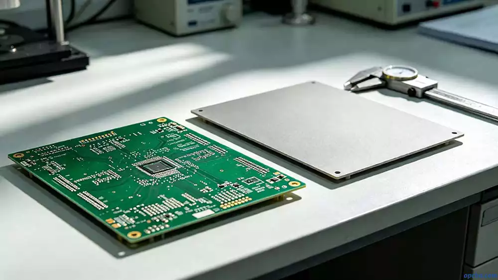
3. Teflon PCB vs FR4: Not Just a Matter of “Better”
How significant is the difference in real-world applications? Here are three representative scenarios:
Scenario 1: 10GHz Microstrip Line, 50Ω Impedance, 0.8mm Board Thickness
- With FR4 (Dk≈4.0–4.8, grade dependent): Trace width varies; attenuation is significantly higher
- With a Teflon PCB material (e.g., Dk≈2.2): Trace width is wider, enabling better impedance control and lower loss
Wider traces mean easier manufacturing and more stable impedance control—a frequently overlooked design advantage of Teflon PCB.
Scenario 2: 28GHz 5G Millimeter Wave
FR4’s dielectric loss at 28GHz is high enough that signal integrity becomes a major challenge over any significant distance. That’s why most 5G millimeter-wave antenna boards use Teflon PCB or other specialized RF laminates.
Scenario 3: 77GHz Automotive Radar
At 77GHz, Dk stability across temperature is critical. FR4’s dielectric properties can shift more significantly with temperature and humidity compared to specialized RF materials, which can cause phase drift in radar systems.
When to Consider Teflon vs. When FR4 May Suffice:
| Frequency Range | Recommendation |
| < 2GHz | FR4 is typically adequate for most designs |
| 2–6GHz | Evaluate loss budget carefully; consider low-loss FR4 or hydrocarbon-based materials like Rogers 4350B |
| 6–20GHz | Low-loss RF laminates (hydrocarbon ceramic, PTFE-based) are often recommended |
| 20–40GHz | PTFE-based or ceramic-filled RF laminates are commonly selected |
| > 40GHz | Advanced PTFE-based or ceramic-filled microwave laminates are typically required |
4. Mainstream Teflon PCB Material Grades (Engineer’s Selection Reference)
Teflon PCB laminates currently on the market come primarily from these suppliers:
| Supplier | Core Series | Material System | Typical Dk (supplier datasheet values) | Typical Applications |
| Rogers | RT/duroid 5880 | PTFE + glass fabric | 2.20 | Aerospace, satellite, high-frequency test |
| Rogers | RO3003 | PTFE + ceramic | 3.00 | 77GHz automotive radar, millimeter-wave |
| Rogers | RO4350B | Hydrocarbon + ceramic | 3.48 | 5G, microwave, power amplifiers |
| Taconic | TLY-5 | PTFE + glass fabric | 2.20 | High-frequency LNBs, military radar |
| Taconic | RF-35 | PTFE + ceramic | 3.50 | Wireless, IoT, commercial RF |
| Arlon | DiClad 880 | PTFE + glass fabric | 2.17 | Antennas, radar systems |
| Nelco | N6000-11 | PTFE + glass fabric | 2.20 | Phased array antennas |
Important clarification: Not all high-frequency materials are PTFE-based. For example, Rogers RO4350B is a hydrocarbon-based material with ceramic filler—not PTFE. It offers good high-frequency performance with much easier processing than PTFE, making it a popular choice for applications up to roughly 20–30GHz.
Selection Decision Framework:
- Frequency: > 20GHz → PTFE-based or advanced ceramic-filled materials become increasingly necessary
- Loss budget: Calculate allowable attenuation and work backward to required Df
- Layer count: Multilayer boards → consider CTE matching between layers
- Fabrication capability: Confirm your PCB supplier has experience with your chosen material system
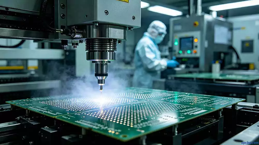
5. Teflon PCB Manufacturing: Key Challenges and Quality Control
A Teflon PCB can cost several times more than a comparable FR4 PCB, depending on material grade, layer count, and fabrication requirements. Understanding why requires looking at the manufacturing challenges—these directly impact quality, yield, and lead time.
5.1 Drilling and Resin Smear
PTFE is inherently soft and ductile. During drilling, heat from the rotating bit can cause the PTFE resin to locally soften and “smear” across the hole wall, covering inner layer copper pads. If this smear isn’t removed, subsequent copper plating won’t form a reliable connection.
Industry best practice: Use specially designed drill bits (often with an “under-cut” geometry), limit bit life more aggressively than with FR4, and optimize feed speeds for the specific PTFE grade being used.
5.2 Via Metallization—Surface Activation Is Required
PTFE has extremely low surface energy—it’s literally the “non-stick” material. Standard electroless copper plating won’t adhere reliably.
The industry’s most widely adopted approach is plasma desmear, which uses plasma-state gas to microscopically roughen the PTFE surface, creating a mechanical key for copper adhesion. It’s a well-established process, though it requires specialized equipment and tight process control.
Sodium-naphthalene etching is an alternative chemical method for activating PTFE surfaces. It’s still used in some production environments—particularly in aerospace and defense applications—but it involves hazardous chemicals that require strict handling and environmental controls.
| If your PCB supplier doesn’t have plasma treatment capability, discuss their specific PTFE processing experience before placing your order. |
5.3 Copper Foil Selection—VLP/HVLP Matters
High-frequency signals exhibit the skin effect—current concentrates in the outermost few micrometers of the copper surface. Standard rough copper foil forces signals to navigate microscopic “peaks and valleys,” effectively increasing conductor loss.
Teflon PCB materials are typically paired with VLP (Very Low Profile) or HVLP (Hyper Very Low Profile) copper foils. These have significantly lower surface roughness compared to standard foils, helping minimize conductor loss.
6. Practical Design Considerations for Teflon PCB
6.1 Impedance Calculation Considerations
When designing a 50Ω microstrip line at 10GHz with 0.8mm board thickness:
- With FR4 (Dk varies): Trace width changes significantly depending on the specific FR4 grade
- With a Teflon PCB material (e.g., Dk≈2.2): The lower Dk results in wider trace widths for the same impedance, which generally improves manufacturability and impedance consistency
The example above illustrates a general principle: low-Dk materials tend to produce wider traces for a given impedance, which can be beneficial for manufacturing. However, actual values depend on your specific stackup, copper thickness, and the exact Dk of the material at your operating frequency.
6.2 Laminate Structure Selection
- Glass fabric reinforced: Good dimensional stability, but be aware of “glass weave effect”—if one trace of a differential pair runs over glass fiber and the other over resin, skew can occur. Consider spread-glass or open-weave fabrics for very high-speed designs.
- Ceramic filled: More uniform Dk distribution, better thermal conductivity, but typically more expensive.
6.3 Storage and Assembly
- Storage: Follow the laminate supplier’s specific storage recommendations. Most PTFE materials should be stored in a controlled environment (18–25°C, dry) and used within the recommended shelf life.
- Pre-bake before assembly: Typically 105°C for 2–4 hours to remove absorbed moisture—check your material’s datasheet.
- Reflow soldering: Nitrogen atmosphere is recommended. Peak temperature around 260°C may be acceptable depending on the specific laminate system and assembly process.
7. Teflon PCB Cost Breakdown
When you receive a quote for a Teflon PCB, prices can vary several-fold across different projects. Understanding the cost structure helps you evaluate quotes—and helps you design within your budget.
7.1 Cost Decomposition
Material Cost (Largest Component)
PTFE laminate pricing is in a completely different range from FR4:
- Chinese-manufactured PTFE laminates: roughly 3–5x FR4
- Imported brands (Rogers/Taconic/Arlon): roughly 5–10x FR4
The cost differences come from: PTFE resin cost, glass/ceramic filler formulations, sensitive production yields, and brand premiums.
| The same RT/duroid 5880 can cost 30%+ less when sourced in Asia compared to the US. Asia has become a major production base for Teflon PCB laminates, with multiple Chinese CCL manufacturers now offering mature PTFE laminate production—which has helped lower overall PCB manufacturing costs for these materials. |
Fabrication Costs
- Drilling: Shorter bit life, tighter parameters → per-hole cost 3–5x FR4
- Surface activation: Plasma or sodium-naphthalene treatment adds significant process cost
- Lamination: Multilayer PTFE boards require longer press cycles and tighter temperature control, impacting throughput
Yield Loss
PTFE’s CTE (coefficient of thermal expansion) makes layer registration more difficult during lamination. More layers and smaller hole sizes reduce yield—and this cost is distributed into the good boards.
7.2 Cost Optimization Strategies at the Design Stage
The most effective cost control happens at the design phase, not during sourcing:
- For projects under roughly 10GHz, consider hydrocarbon-based materials like Rogers 4350B—they process much more like FR4 and can cost 30–50% less than PTFE-based options
- Minimize layer count—each additional PTFE lamination layer increases cost and reduces yield
- Avoid extreme minimum hole diameters—adding just 0.05mm of margin can significantly improve hole wall quality and yield, actually lowering overall cost
- Check material availability before finalizing your grade selection—different fabricators stock different PTFE grades. If you specify a grade not regularly stocked, lead times can extend 2–3 weeks, and you may need to purchase full panels. A quick conversation about availability and lead time often saves money and delays
These recommendations come from issues we encounter daily when handling Teflon PCB orders. If you’re planning a high-frequency project and have questions about material selection or design trade-offs, reach out to the OPCBA engineering team—we can provide a selection and cost assessment based on your specific requirements.
8. Typical Application Scenarios and Selection Recommendations
| Application | Common Material Choices | Critical Requirements |
| 5G Sub-6GHz | RO4350B, MEGTRON, low-loss FR4 | Stable Dk, cost-effectiveness |
| 5G mmWave (28/39GHz) | RO3003, TLY-5, RT/duroid 5880 | Low loss, phase stability, consistency |
| Automotive Radar (77GHz) | RO3003, TLY-5 | Dk temperature stability, tight impedance control |
| Satellite Communications | RT/duroid 5880, RT/duroid 6002 | Low outgassing, thermal stability, radiation tolerance |
| Aerospace/Defense | RT/duroid 5880, DiClad 880 | Reliability, extreme environments, certified processes |
| High-Power RF | Ceramic-filled PTFE, RO4350B | Thermal management, high power handling |
Closing Thoughts
Teflon PCB materials aren’t a magic solution—they’re more expensive, more difficult to process, and require more careful material selection than standard FR4. But for high-frequency, high-reliability applications, they’re often the right choice.
The key isn’t simply “Teflon vs. FR4″—it’s frequency, loss budget, manufacturing capability, and cost working together. We hope this guide helps you make more informed decisions on your next high-frequency project.