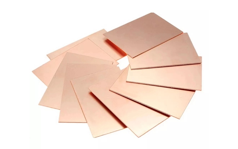
Copper-clad laminate (CCL) is the sheet material that sits underneath every copper trace on a rigid PCB. Manufacturers bond one or two layers of electrolytic copper foil to an insulating substrate, usually glass fiber cloth, polyimide film, or a metal core, under heat and pressure. The result is a composite sheet in which the conductive layers and the insulating layers depend on each other: the foil carries the signal, the base carries everything else.
Every property a finished PCB has, from signal speed to thermal reliability, starts here. CCL determines how fast signals travel, how much energy they lose on the way, and whether the board survives reflow, thermal cycling and years of operation. This page covers how CCL is classified, which performance metrics matter, how its three functional layers work, and where specific grades fit in high-reliability designs.
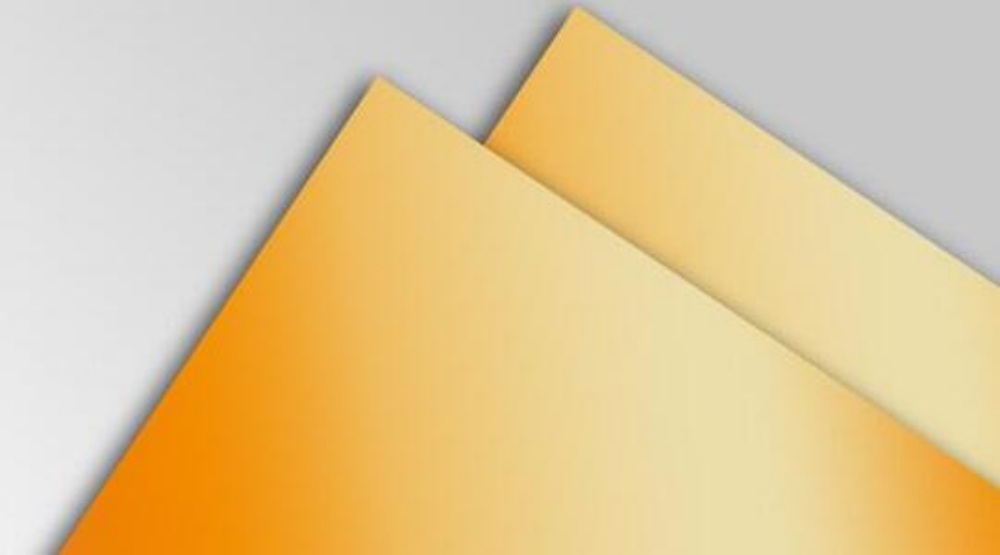
Concept and classification of copper clad laminates
The production route has changed little in decades: take glass fiber fabric (or paper for the cheapest grades), soak it in resin until it becomes prepreg, stack it with copper foil on one or both sides, and press the stack under heat until the resin cures. What separates one CCL grade from another is the resin system, the glass style and the foil type chosen for that stack.
By application and environmental performance, the industry generally sorts CCL into four groups:
- Standard rigid grades, including conventional FR-4, lead-free compatible variants and halogen-free versions. These cover the majority of consumer and industrial boards.
- High-speed substrates, engineered for low Dk and low Df so that signals above a few GHz arrive with acceptable attenuation.
- Automotive-grade laminates, qualified for sustained high temperature, thermal shock and vibration in engine compartments and safety systems.
- IC packaging substrates, the finest-pitch end of the family, where dimensional stability at small feature sizes matters more than raw electrical performance.
A fifth category, flexible copper-clad laminate (FCCL), uses polyimide film instead of glass cloth. FCCL is what makes wearables, foldable phones and flex-rigid builds possible, and it is judged by a different set of metrics, covered below.
For a closer look at how the laminate stage differs from the PCB fabrication stage, see the difference between CCL and PCB production.
Performance metrics of copper-clad laminates
Performance covers physical, chemical, electrical and environmental dimensions. Electrical behavior is the core indicator, because the laminate sits inside every signal path on the board. For flex and flex-rigid applications, bend life and temperature resistance join the list as first-order requirements.
Different sectors pull these requirements in different directions. Telecom and data-center hardware needs low dielectric constant (Dk below about 3.0) and low loss factor (Df below about 0.005) so that signals survive long transmission lines. Wearable FCCL is judged first on bend life, commonly specified above 100,000 cycles at a 5 mm radius, while automotive flex applications typically require more than 50,000 cycles at a 10 mm radius plus tolerance to much wider temperature swings.
Environmental ratings tighten just as fast. Standard FCCL is expected to survive temperature cycling from -55°C to 125°C; automotive under-hood applications push the low end to -40°C and the high end to 150°C; and flex circuits destined for medical devices must also tolerate repeated high-temperature sterilization around 180°C. Thickness tolerance follows the same pattern, with FCCL commonly held to ±5% against the ±10% that is accepted for rigid laminate.
The figures above are widely used engineering reference points for specifying laminate families. Exact qualification values always come from the laminate manufacturer’s datasheet for the specific grade and thickness, so confirm them against the current revision before locking a stack-up.
Core functional properties of CCL
A CCL sheet does three jobs at once, and each layer of its structure maps to one of them.
Copper foil: the conductive layer
The foil provides the low-impedance path for signal traces and power or ground planes. Foil thickness sets the current-carrying capacity: 12 μm foil is common on fine-line HDI boards where currents are small, while 105 μm foil on high-power boards carries tens of amperes.
Surface condition matters even more at high frequency. Above roughly 1 GHz, current crowds into a thin skin depth at the conductor surface, and the skin depth shrinks as frequency rises, to around 0.66 μm in copper at 10 GHz. When foil roughness is comparable to or larger than the skin depth, the current path lengthens along the surface contours and conductor loss climbs. That is why high-speed grades specify very-low-roughness or rolled foil, and why foil roughness shows up in every serious 10G-plus stack-up review.
The base layer: insulation and signal environment
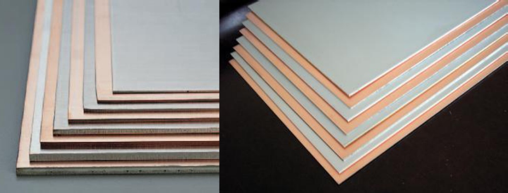
The glass-cloth-plus-resin core (or polyimide film in FCCL) insulates layers from each other and from the outside world, and its parameters set the signal environment for the whole board. The ones that matter most:
- Dielectric constant (Dk) reflects how much the substrate polarizes in an electromagnetic field, and it sets propagation speed within the board. Standard FR-4 runs around 4.2 to 4.5 at 1 GHz; low-loss grades reach the low 3s; PTFE-based high-frequency laminates can go as low as 2.2.
- Dissipation factor (Df) is the share of energy lost per field cycle, and it directly drives attenuation. Lower is always better for signal integrity, and the difference between Df families is what separates a consumer board from a 25G+ SerDes channel.
Between them, Dk and Df decide who a laminate is for. A grade lives or dies on how these two numbers hold up across frequency, temperature and resin content.
Mechanical and thermal behavior
As the backbone of the PCB, the laminate must stay dimensionally stable through stress, vibration and thermal shock. The key parameters:
- Glass transition temperature (Tg) marks where the resin softens and mechanical properties drop off. Standard FR-4 sits near 135°C; high-Tg grades reach 170°C and above; automotive-grade laminate is expected to hold above that threshold through engine-compartment temperatures.
- Coefficient of thermal expansion (CTE) runs around 50 to 70 ppm/°C in the Z-axis against copper’s 17, and roughly 15 to 20 ppm/°C in-plane, set mainly by the glass cloth. Z-axis CTE mismatch is the root cause of plated via cracking during thermal cycling, which is why low-CTE laminate matters for any board that sees reflow plus a long service life.
These numbers explain most field failures that get blamed on “the board”: via cracking traces back to Z-CTE, delamination traces back to Tg margin, and attenuation failures trace back to Df and foil roughness.
Common laminate grades in high-reliability designs
Classification tells you what a laminate family does. Specific grades tell you what to order. For high-layer-count boards that need more thermal margin than standard FR-4, what Isola 370HR is covers the most widely used high-Tg epoxy system. If the decision is between that grade and a conventional build, choosing between 370HR and standard FR-4 walks through the trade-offs. When the stack-up and tolerances are already fixed, the 370HR property values and test methods list the numbers fabricators quote against. And for low-loss applications beyond the FR-4 family, Isola FR408HR is a common next step.
Summary
Rigid CCL supports fixed-assembly electronics; FCCL opens up bendable and conformable products. Across both families the selection logic is the same: match Dk and Df to the signal requirements, match Tg and CTE to the thermal profile the board will actually see, and match the grade to the qualification environment of the end product. Getting the laminate decision right at the start is cheaper than re-engineering the stack-up after the first reliability failure.
If you are specifying material for a new build, send us the stack-up, layer count and target certifications, and our engineering team will help you pick a grade that fits both the design and the production process. Our multilayer PCB fabrication team works with the full range of grades described above.